All reading editions · Original PDF
Raven Owner's Manual
INTRODUCTION
Congratulations! You are now the owner of one of the finest foot-launched soaring flex-wings manufactured today. Your Wills Wing Raven is the product of an extensive design and development program aimed at optimizing your level of safety as a pilot, while providing you with the highest level of effective soaring performance available in the sport today.
Please read and be sure you thoroughly understand this manual before flying your Raven. Hang gliding is an extremely demanding sport requiring exceptional levels of attention, judgement, maturity, and self discipline. It is extremely unlikely that you will be able to participate in it safely unless you make a conscious and continual commitment to your own safety. Be sure you are thoroughly familiar with the set-up, pre-flight, and breakdown procedures described in this manual, and work these procedures into a standard routine so that they become habitual. Never take anything for granted in flying; if you are in doubt about anything, stop and figure it out or consult your manual, your dealer, or Wills Wing, Inc.
We would like to welcome you to the Wills Wing family of pilots, and we wish you a safe and enjoyable flying career.
TECHNICAL INFORMATION
Your Wills Wing Raven was designed specifically for footlaunched soaring flight, and represents a state of the art execution of the concept of a footlaunched, weightshift controlled ultralight soaring aircraft. The Raven has been tested and certified as complying with the Hang Glider Manufacturer's Association 1980 Airworthiness Standards for utility class flex wings. The Raven was not designed to be towed, tethered, or motorized, or flown by more than one person at a time. We specifically recommend that you not attempt to fly your Raven in any of these ways. Should you decide to do so, please proceed with extreme caution and avail yourself of the experience and expertise of those people who are qualified in that particular area. Please be advised that Wills Wing can in no way guarantee or be responsible for the airworthiness of or applicabiltiy to any specific purpose of any Wills Wing glider, except as described in the HGMA airworthiness standards.
Stall speed of the Raven at maximum recommended wing loading is 22 mph. (Note: this figure represents the actual airspeed of the glider at stall, indicated airspeed on a control bar mounted airspeed indicator will be about 7 to 10 miles per hour lower.)
Top speed of the Raven at minimum recommended wing loading is 39 mph.
The recommended pilot weight range for the Raven (pilot flying weight including harness, helmet, parachute, instruments, and any other accessories) is:
Raven 229 170 to 230 pounds
Raven 209 150 to 210 pounds
Raven 179 125 to 170 pounds
Raven 149 90 to 140 pounds
Flight operation of the Raven should be limited to non-acrobatic manuevers, i.e. those in which the pitch angle will not exceed either \( 30^{\circ} \) nose up or nose down from the horizon, and in which the bank angle will not exceed \( 60^{\circ} \) .
The Raven will strongly resist spinning and will tend to recover immediately from a spin without entering extreme or unusual attitudes.
TECHNICAL INFORMATION (continued)
The positive limit load of the Raven is 3 G's.
The negative limit load of the Raven is 1.5 G's.
NOTE: Limit loads are defined as the maximum loads to be expected in normal flight operation. THEY DO NOT represent the ultimate loads which the glider is capable of withstanding without failure. The Raven has been tested to more than six G's positive without any permanent deformation of the glider's structure. The Raven has been tested under negative load to the limits prescribed in the HGMA standards, and has been found to exceed the prescribed load limits by a significant margin.
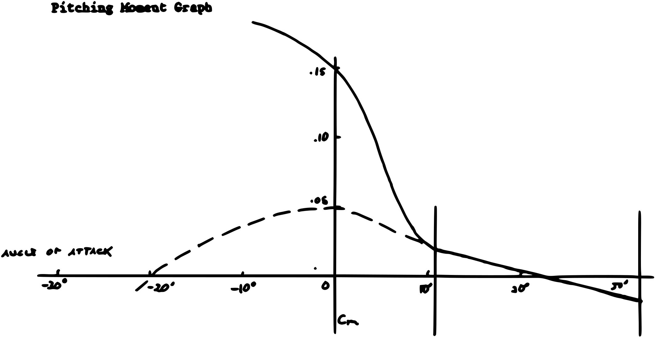
One aspect of HGMA testing that is extremely important with regard to pilot safety is the test of the glider's pitching moment coefficient. This is a number which measures the tendency of the glider to pitch nose up or nose down. A large positive value indicates a strong tendency to pitch nose up, a small positive value indicates a weak tendency to pitch nose up, a negative value indicates a tendency to pitch nose down. The HGMA standards require that the pitching moment coefficient be measured and plotted on a graph as a function of different angles of attack. The resulting curve must conform to certain minimum requirements. The dotted line indicates a minimum acceptable pitching curve, and the solid line indicates the Raven pitching moment curve. The vertical brackets indicate the range of angles of attack involved in the normal operating speed range of the glider. It is in this range of speeds and angles of attack that the pilot can feel the pitching moment directly as bar pressure. At lower angles of attack, the pitching moment can not be felt by the pilot, but it is at these lower angles of attack, particularly in the range near zero angle of attack, that a strong positive pitching moment is extremely important in reducing the chance of a turbulence induced pitchover.
A USHGA proficiency level of Hang III (intermediate) is necessary for the safe operation of the Raven. Operation of this aircraft by anyone not possessing this or a higher level of proficiency is prohibited and may be dangerous. Please consult this manual, your dealer, or Wills Wing for other information regarding the flight characteristics of the Raven.
RAVEN ASSEMBLY PROCEDURE
Your Raven should be delivered to you fully assembled, inspected, and test flown by your dealer. If this is not the case, you should contact Wills Wing. Should you need to assemble your Raven out of the shipping tube, the following instructions should help. You will need a screwdriver and two 7/16" wrenches for assembly.
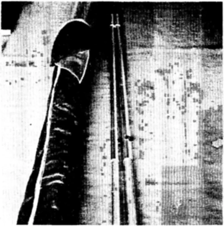
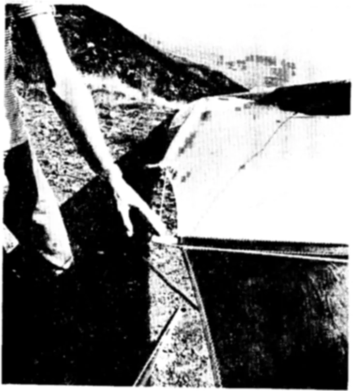
1) First, remove the endcap from the shipping tube and unpack the shipper (picture 1.)
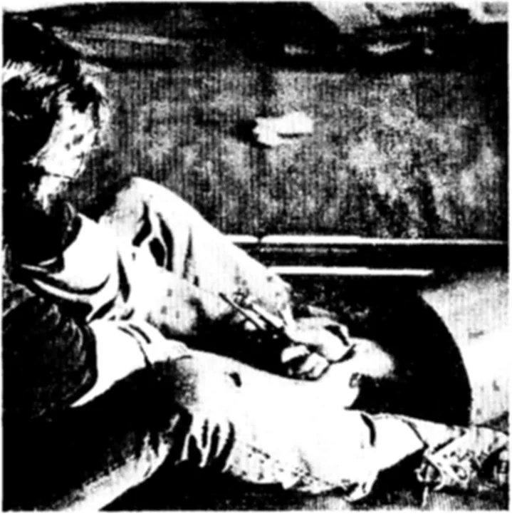
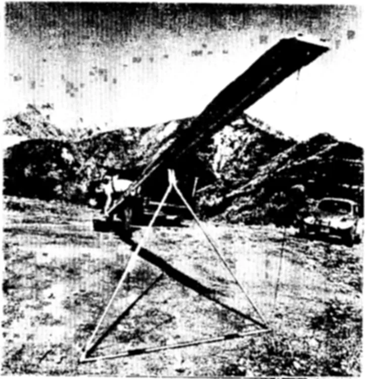
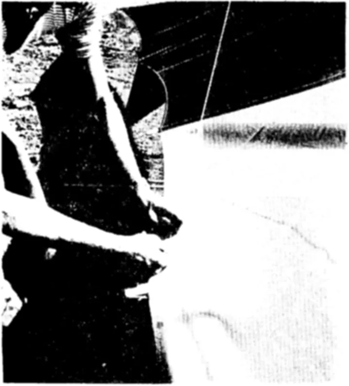
2) Carefully remove the glider and rear leading edges from the tube (picture 2.)
(If the glider was shipped full length, it will already be assembled.)
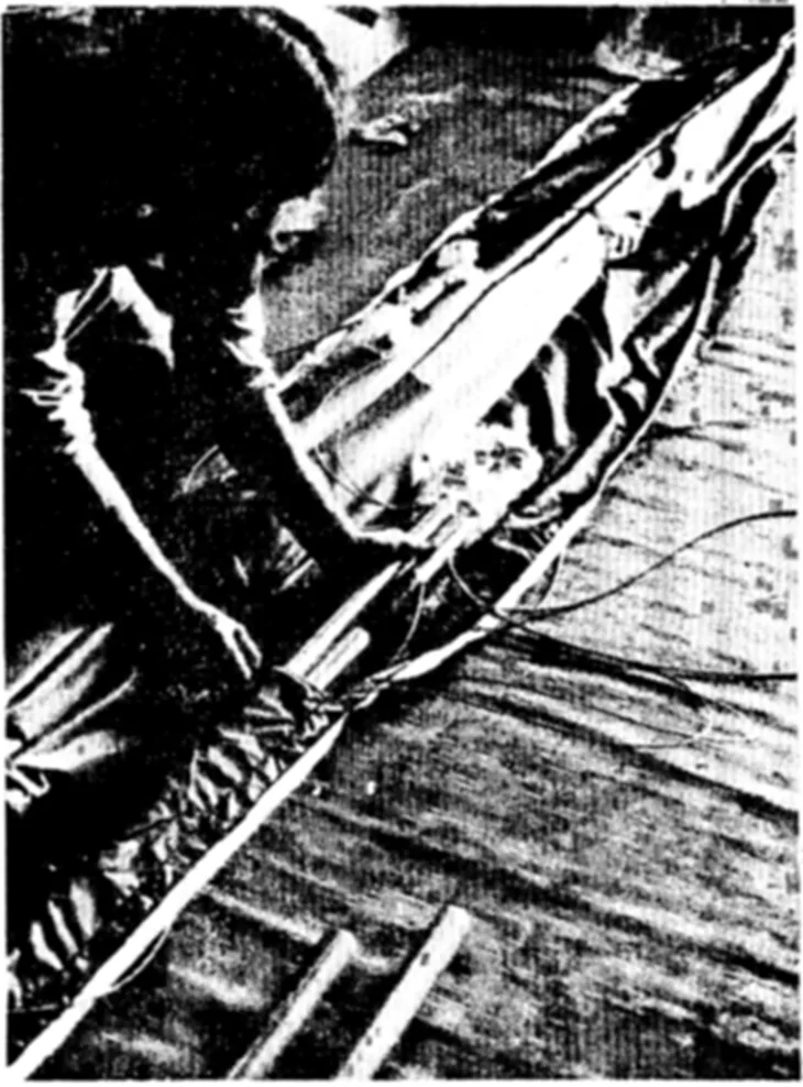
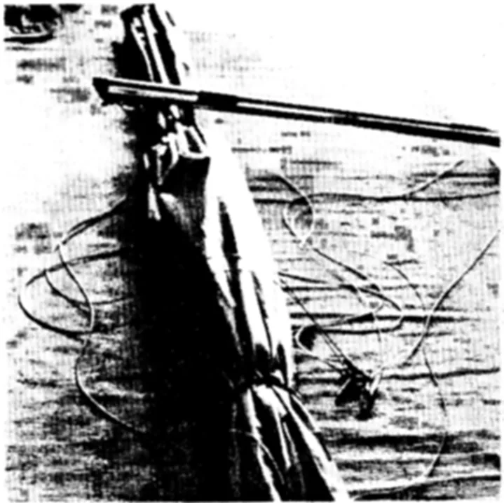
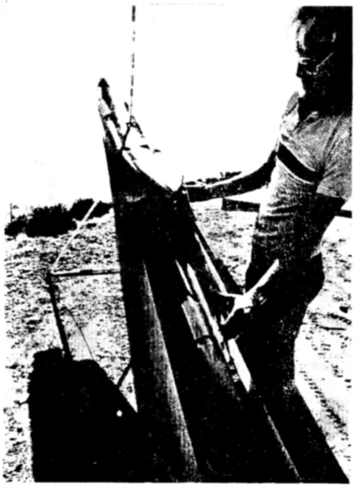
3) Unzip the glider coverbag. (picture 3.)
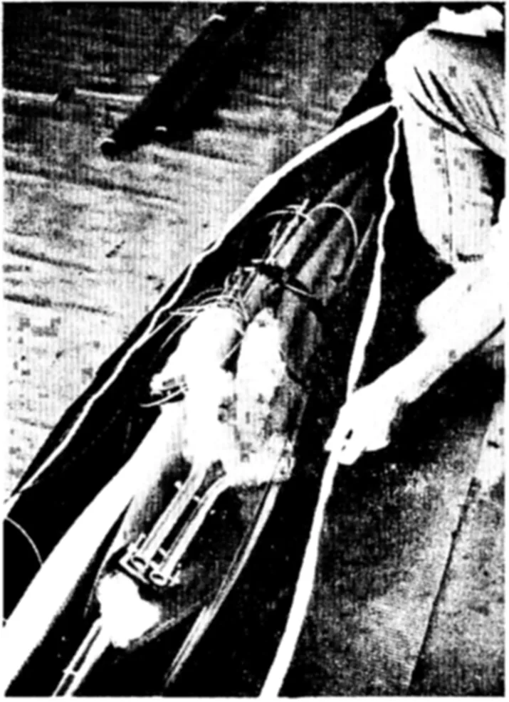
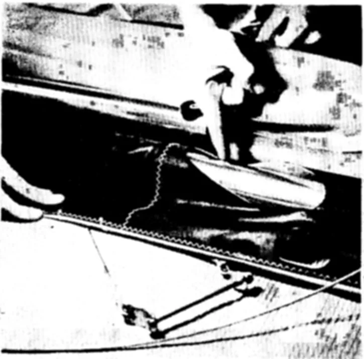
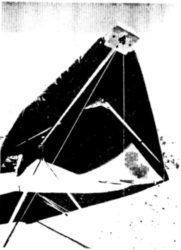
4) Remove control bar from pocket in coverbag. (picture 4) Remove protective packing material from control bar and control bar neck.
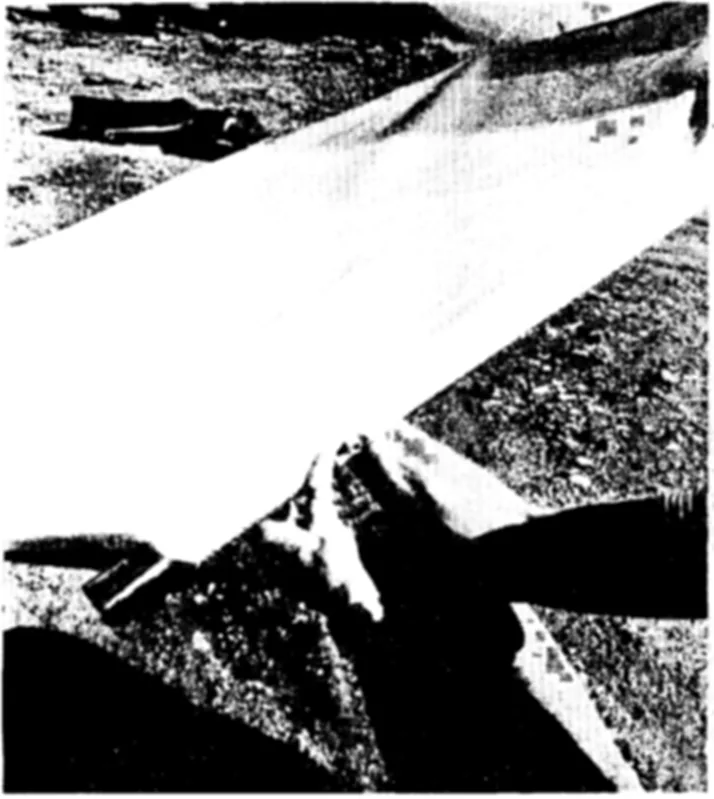
5) Remove bag completely from glider. Lay out control bar and flying wires, checking at the rear flying wire eyebolt to see that the the wires are not twisted and are laid out on the appropriate side of the glider. (picture 5).
6) The glider should now be laying on its back, with the control bar bracket and neck facing upwards. We will at times talk about the glider's right and left sides, by which we mean the glider's intrinsic right or left, i.e. what would be the pilot's right or left while flying the glider. To determine the glider's right and left while in its current position, lay on your back next to the glider with your head towards the noseplate and your feet towards the tail. Your right is now the glider's right. With the glider on its back, slide the leading edges (rear) into the sail from the rear, taking care that the leading edge marked "R" goes into the right side and the leading edge marked "L" goes into the left side. Note that the clevis pins will have to be removed before assembly, and that the saddles on the leading edge should face downward. Be sure to insert the clevis pin and safety to secure the leading edge after assembly. (picture 6)
7) Insert the crossbar into the opening in the sail. (picture7)
8) Refer to picture 8 for the proper relative assembly sequence of the leading edge, crossbar, leading edge/crossbar bolt, side flying wire and kingpost side wire. Be sure as you assemble the leading edge/crossbar junction that the wires are not crossed or tangled.
9) Refer to picture 9 for the correct completed assembly of the leading edge crossbar junction. Loosen the nylock nut slightly after inserting the safety ring.
10) Remove the sheet metal screws from the rear of the leading edges and re-install picture 4
picture 3
Picture 2
picture 1
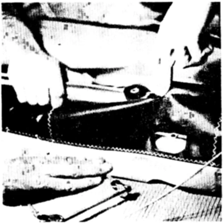
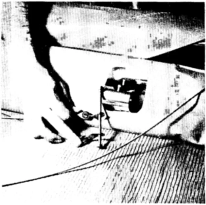
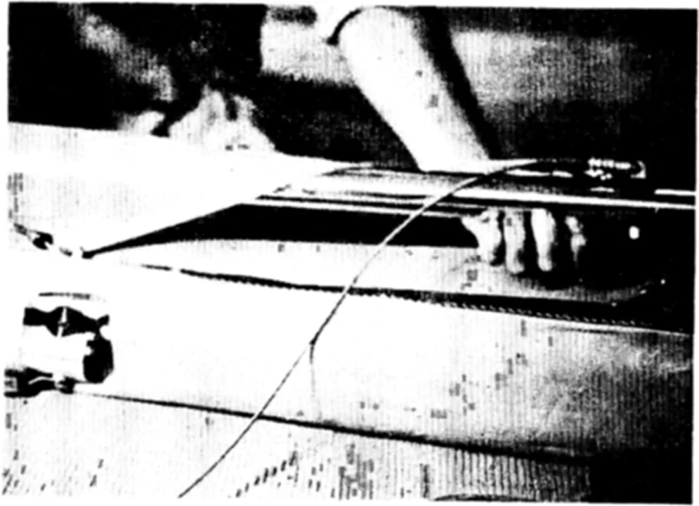
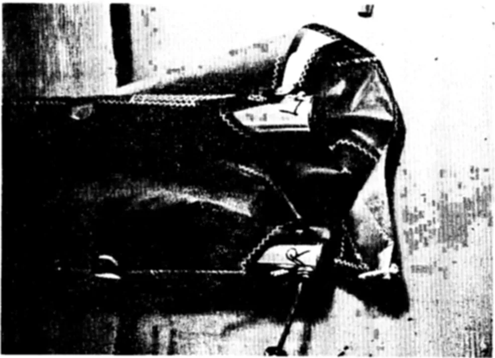
through the sail adjuster grommets as shown in picture 10. Check again to make sure that the left and right leading edges are installed in the correct sides of the glider. (See instruction #6).
Your glider should now be properly assembled and ready to set up. A description of the proper set up procedure follows. After you set up your glider for the first time, you should check every nut, bolt, screw and fitting on the glider to make sure all are secure. Nuts, bolts and screws should not be overtightened, but should always be snug and secure.
RAVEN SET-UP PROCEDURE
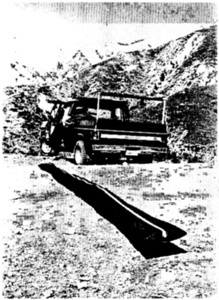
1) Lay the glider on the ground, nose into the wind, with the zipper (and control bar bracket) facing upwards. (picture #1)
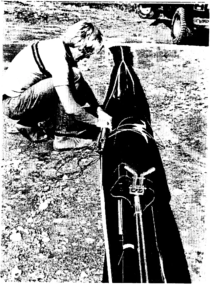
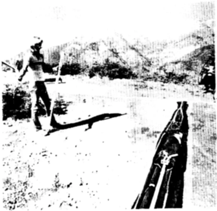
2) Unzip the bag, and remove the control bar from the pocket in the side of the bag. (picture #2). Take care to slide the bar straight out of the pocket, without twisting or turning the bar, and then walk straight away from the glider while holding the control bar. (picture 3). Using this procedure should help you avoid the problem of tangling the flying wires. Check to be sure that the wires are not tangled or twisted before proceeding further.
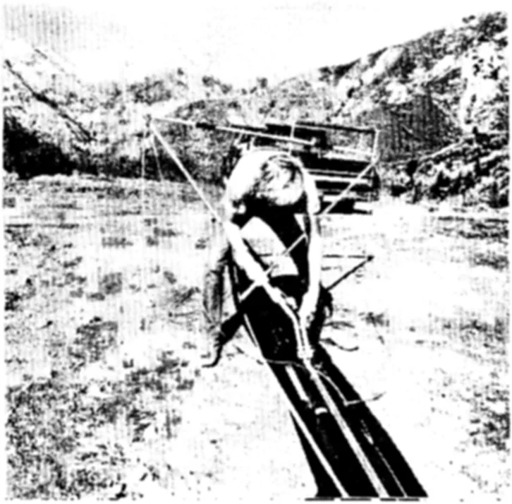
3) Unfold the control bar and cross the uprights about three inches from the end. (picture 4) Grasping the junction of the uprights in one hand, with the uprights resting against your thighs as shown, lift the control bar neck with your other hand and fit the uprights on to the neck one at a time.
4) Remove the clevis pins and safety rings, slide the uprights down onto the neck until the holes are aligned, and reinstall the clevis pins and safety rings. The clevis pins should be installed so that the safety rings are on the outside of the uprights, otherwise the safety rings may become caught in your harness and pulled loose.
5) Grasp the tang at the front end of the flying wires and pull it towards the nose. Remove the wingnut and safety from the bolt on the underside of the noseplate and attach the tang at this point. Take care not to allow the bolt to fall out of the noseplate during this assembly. Reinstall the wingnut and safety.
6) Check all thimble connections to see that there are no crossed or twisted thimbles. Flip the glider upright onto the control bar, and remove the bag. (picture #6)
7) Remove all of the velcro ties and put them in your pocket. Remove the protector bag from the tail end of the keel. Drop the sail to the outsides of the leading edges, allowing it to unroll partially. Lift the kingpost, and grasp the rear kingpost wire. Pass it through the webbing loop on top of the rear of the sail, and fit the tubular fitting onto the quick release tensioner at the rear of the keel. (picture 7). Check again to see that there are no crossed or twisted thimbles and then snap the quick release shut.
8) At this point, if the winds are five mph or less, the glider should be left facing nose into the wind. If the wind is more than five mph, but steady in speed and direction, place the glider crosswind, with the tail just slightly into the wind. If the wind is gusty or switching direction, you will need to have a helper to stand on the control bar base tube. If the wind is more than 20 mph, or gusting more than 10 mph differential, you should not set up at all, as it is probably unsafe to fly.
9) When you have positioned the glider properly, deploy one wing most of the way. (picture 8) Slide the protector bag off to one side of the crossbar center plates. Deploy the other wing all the way. Check for crossed thimbles on the side wires.
10) Remove the safety, wingnut, and bolt which secures the crossbar from the keel. Slide the bolt halfway up through the same hole from the bottom, and hold it there with one hand. Grasp the crossbar with your other hand and push back until the holes in the plates line up with the bolt. Lower the crossbar over the bolt, and push the bolt up through from underneath. (picture 9)
11) Install the wingnut and safety ring. (picture 10).
12) Install all battens (order is by length, shortest at the tip, longest at the root). Make sure to install battens with the thin end forward. (picture 11)
13) Lift reflex support post and fit lower end over the rivet on top of the keel. (picture 12).
14) Install the washout control tips into the leading edge from the inside and secure with the safety ring. (picture 13)
15) Place all velcros except one inside the keel pocket protector bag, slip this
inside the crossbar protector bag, and use the remaining velcro to secure this neatly to the crossbar.(picture 14)
16) Get all your flight gear out of the transport truck, and put your glider bag in.
17) Do a complete walk around inspection of the glider, checking every part and every assembly. Make sure all nuts are secure, all wing nuts safetied, no twisted thimbles, no tears in sail, no dents in tubes, no frayed cables, etc. Sight the keel and leading edges, they should be straight. The leading edges may appear to have a slight inward bow, this is normal, but they should be symmetrical, and they should not be bent.
18) Do a harness check. Make sure the glider is rigged for prone if you intend to fly prone, or that it is rigged for supine if you plan to fly supine. All Ravens are rigged for prone unless specially ordered with supine rigging. If rigged for supine, there will be a sticker on the bottom noseplate and on the crossbar indicating that the glider is rigged for supine. Since these parts may have been replaced on a used glider, make sure you know what type of rigging the glider has if you are not the original owner. If you are flying prone, you should be hanging high enough from the base tube that your harness and parachute clear the bar throughout the entire range of pitch control. You should not hang more than six inches above the base tube, as this would adversely affect in flight control of the glider. The hang loop bolted to the keel is the primary suspension for the pilot. A second safety suspension loop should be attached to the neck of the control bar at the top bolt. This safety should be just long enough so that it maintains some slack throughout the entire range of pitch and roll control.
19) You should now be ready to fly. Check the conditions carefully, and be sure you are completely prepared, mentally and physically for the flight. Attach the reflex support bridle. Make sure that the bridle is not looped under the batten just inboard of the batten at which it attaches. (pictures 15 and 16) (Note: this cannot happen on a 229, since the bridle batten is the inboard most batten.)
20) Place your upper arms inside the uprights, grasp the uprights, and lift the glider. If the wind is more than 10 mph or is gusty, have an assistant on your nose wires. The glider will be much easier to ground handle if you allow it to assume a nose up attitude. Carry the glider to launch and set it down. Do not ever put the nose down in any wind of more than 10 mph with the bridle
picture 16
system attached. If you do, you risk breaking the bridle battens, and/or having the glider pitch its nose up, take off and fly away. Check the conditions again, clear the airspace in front of launch, and clear any spectators. Hook into the glider. Check to see that you have hooked into the glider. Check again. Put your helmet on. If you are being wire launched, verify your release signal and procedure with your wire man. Lift the glider, hold in a nose high attitude, clear your wire man and/or any spectators, and give a good agressive take off run. Push out.
HAVE A GOOD ONE!
DISASSEMBLY PROCEDURE
Immediately after landing, unhook from the glider. Hold the glider nose into the wind, and swing one wing forward while lowering the tail until the glider is resting on the tail, crosswind, with the tail slightly into the wind. If the wind is more than ten mph, have an assistant on the forward moving leading edge at the crossbar junction to prevent a groundloop. Disconnect the bridle.
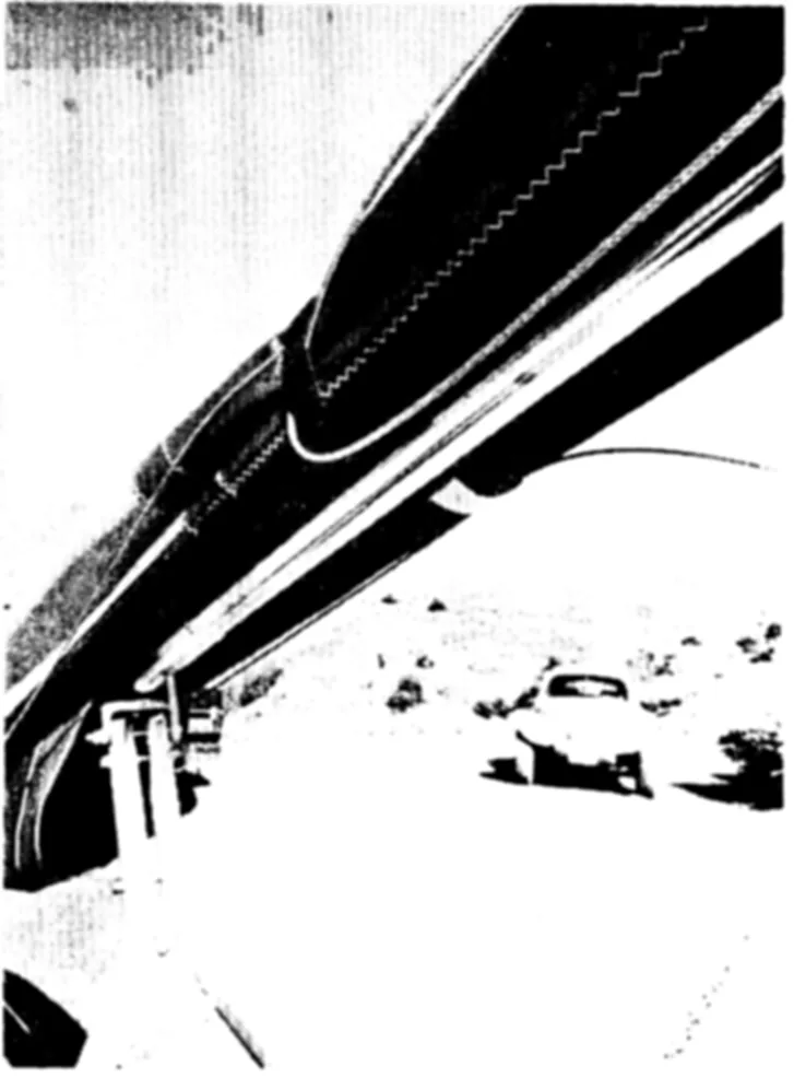
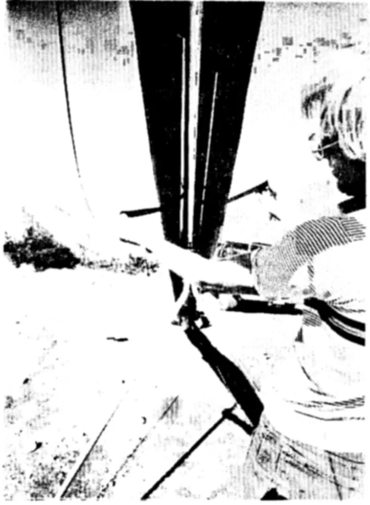
Remove the battens and washout tips, and remove the crossbar anchor bolt, reinstalling it in the keel with the bolt head on top. Be sure to replace the protector bag over the crossbar center plates. (picture 1) When folding in the leading edges, pull the sail over the top of the leading edges, taking care not to set the ends of the leading edges on top of the tips. Undo the tubular fitting on the rear kingpost wire from the quick release, and replace the protector bag over the end of the keel and quick release. Lift the reflex support post and disengage from the rivet on top of the keel. Pull the sail out to the side of the glider, finding the foldover point at which the top and bottom halves are both snug. Take care that the keel pocket is not pulled off to one side. Roll the sail around the battens and washout tip, and continue the roll over the top of the leading edges and down in between the leading edges, securing the roll with a loosely applied velcro strap. The kingpost side wire tangs should be visible on top of the leading edges. (picture 2) Reach in between the leading edges and grasp the sail and reflex support post and pull upwards, lifting the post above the leading edges (picture 2).
Next, clip the bridle to the tubular fitting on the rear kingpost wire. This will help you find the bridle next time you set up the glider. Lay the kingpost down, taking care to slide the center batten slightly to one side so that the batten is not crushed between the kingpost and the head of the crossbar anchor bolt. (Note; this bolt should be stored with the head on top of the keel, even though when the glider is assembled, the bolt is reversed. Another alternative is to store the crossbar anchor bolt on the control bar neck, using the safety ring to secure it.) Tuck the kingpost rear wire and bridle cord into the rolled up sail.
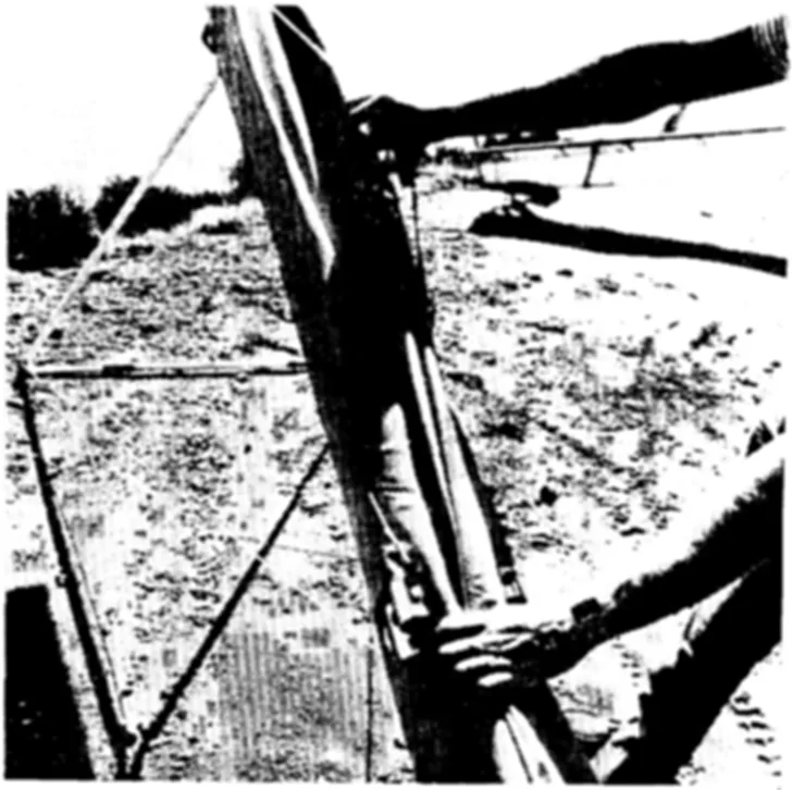
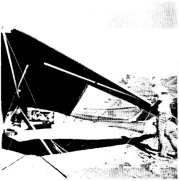
Next, pass a velcro tie over the top of the keel through the loop formed by the front kingpost wire, and around the leading edges. (picture 3) Lift the leading edges with one hand and secure this velcro snugly with the other hand. This velcro holds the kingpost in place, and when applied as shown, will prevent the leading edges from wearing against the corners of the control bar bracket. (picture 4) It is very important that this velcro be properly applied to protect the leading edges and sail from damage.
Return to the rear of the glider and lift the reflex support post so that it points towards the nose and lays against the under side of the sail inside the keel pocket. Squeeze the sail together around the post and roll the pocket slightly, tucking the roll down in between the leading edges while tightening the velcro you applied earlier at this point. This will keep the reflex post from damaging the sail or leading edges. (picture 5)
Unroll the tips slightly, fold the tip in and re-roll. (picture 6) Place a velcro loosely at this point. (picture 7)
Put the bag on the glider, flip it over and lay it down. Disconnect the flying wires at the nose, and remove the control bar from the neck. Fold the uprights to the base tube and walk toward the nose of the glider, keeping the wires straight. Holding the control bar and facing the tail, swing your left hand towards the tail, flop the wires over to the other side of the bag from the side with the control bar pocket, and slide the bar into the pocket. Gather the loose wires and carefully tuck them under the velcro at the rear of the keel. Zip up the bag.
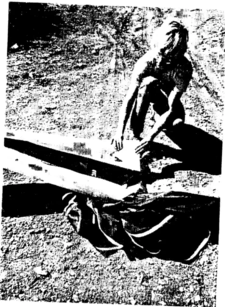
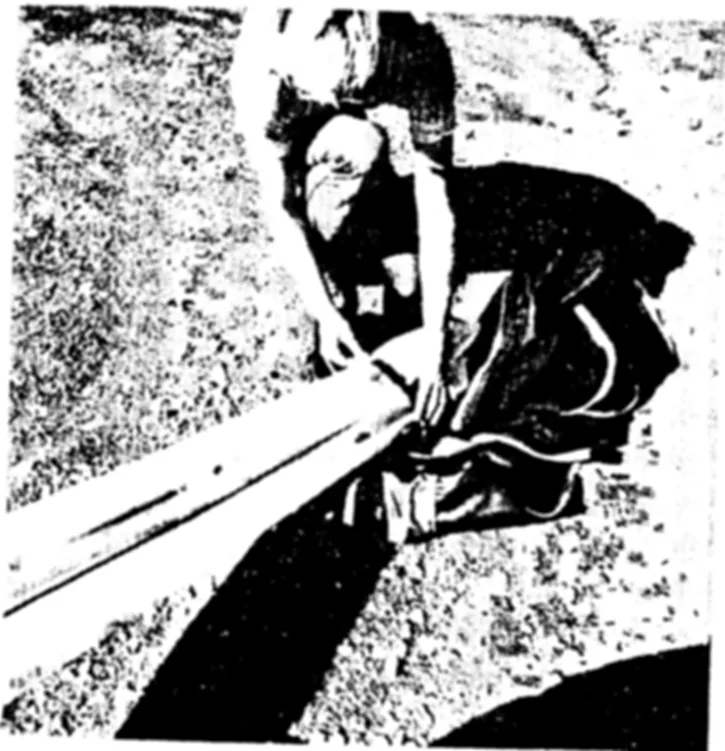
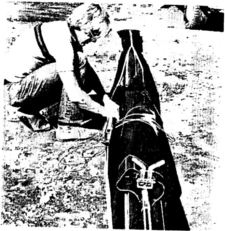
GROUND HANDLING YOUR RAVEN
You will find it much easier to ground handle your Raven with the washout tips and reflex support bridle disengaged. Be sure to attach these systems before launching. Your Raven should not be set nose down in the wind with the bridle and tips attached, as it will tend to pitch the nose up, take off and fly away. There is also a risk of breaking the bridle battens in this situation if the wind is strong enough. Always disconnect the bridle, tips, and reflex support post before leaving your Raven unattended. Never leave your glider assembled and unattended in strong or gusty winds.
FLYING YOUR RAVEN
The Raven is a very responsive and sensitive glider, and is generally roll neutral. You may find the light control pressures and quick response unsettling at first, especially if you are accustomed to flying a less sensitive design. You should make your first few flights from a familiar site in mild conditions, and concentrate on controlling the glider by the gentle application of control pressures, rather than large scale movements along the control bar. Keep in mind that the bar position on the Raven is fairly far out, and that it will respond very well even at very low flying speeds. Resist the temptation to pull the bar in for extra control, as this will tend to lead to overcontrol and roll/yaw oscillations. If you simultaneously pull in and pull over on the bar, the Raven will accelerate very rapidly, with a rapid and significant loss of altitude.
The Raven is trimmed at minimum sink and is roll neutral. This tuning configuration minimizes the physical effort required to effectively work thermal lift. Once you become accustomed to the Raven's handling characteristics, you will find that they serve to significantly increase the effective soaring performance of the glider in a wide variety of conditions.
TUNING YOUR RAVEN
Your Raven comes to you test flown from the factory, and should also have been test flown by your dealer. It is unlikely that you can improve the flight characteristics of the glider by changing the tuning, and you should resist the temptation to tune your Raven unless you are quite sure that it is not flying properly and that you know what you are doing. Before making any adjustments, consult your dealer or Wills Wing.
There are basically only three tuning adjustments on the Raven; the sail adjusters at the rear of each leading edge, and the sail adjuster at the rear of the keel pocket. Tightening these adjusters reduces the camber in the wing, raising the stall speed, making the stall more abrupt, and increasing the control pressures involved in roll control, especially at low speeds. If these adjustments are too loose, the glider will feel sloppy in roll response, especially during roll reversals, and the high speed performance will be reduced slightly. If one leading edge is tighter than the other, the glider will tend to turn towards the side that is looser. A slight tendency to turn can thus usually be corrected by adjusting the sail. Any strong tendency to turn to one side indicates a bent leading edge, which should be replaced. When making adjustments in the sail tension, be sure to carefully mark the original position of the sail at the rear of the leading edge, so that you can verify the amount of adjustment. You should not change the position of the sail more than \( \frac{1}{4} \) " per adjustment, and not more than \( \frac{1}{2} \) " per side.
MAINTENANCE
You should perform a careful inspection of your glider on a regular basis; about twice a year, every thirty hours of airtime, or any time you have reason to suspect that your glider has been damaged. This should involve a complete disassembly of the glider, removing the sail from the frame, and inspecting every nut, bolt, cable, fitting, etc, on the glider. Your Wills Wing dealer is the most qualified person to perform this service, and we strongly suggest that you refer your service needs to your dealer. Bent bolts, frayed or kinked cables, bent gouged or dented tubes, all nylock nuts, and any part about which you have any doubt should be replaced.
Hang loops, and all cables should be replaced once a year, regardless of their apparent condition. (You should also replace the main support straps on your harness once a year.) Any cable, hang loop (or harness strap) that shows any sign of wear should be replaced immediately. Any tears or defects in the sail should be repaired by a professional sailmaker. If your glider is ever exposed to salt water you should wash it immediately and thoroughly rinse it with fresh water, then dry it completely. Anytime your glider is exposed to water, you should remove the endcaps from all tubes and swab the inside with an oil dampened rag. Your sail should never be washed with anything other than fresh water; any soap or detergent will likely damage the sail cloth and reduce its life, and may possibly change the flying characteristics of the glider.
CAR TOP MOUNTING
Your Raven should be mounted on your rack with the control bar bracket facing upwards (upside down). Your rack should have at least three support points (four is better) spanning at least 13 feet of the glider. No more than four feet of the tail end of the glider should extend beyond the last support. All supports should be heavily padded and as wide as possible to distribute the load (4" is good.)
A FEW LAST WORDS
Your Wills Wing Raven is a sophisticated high performance flex wing which will provide you with years of safe and enjoyable soaring. Treat it properly and always maintain a healthy respect for the demands and potential dangers of flying. See you in the sky!
ADDENDUM FOR ALTERNATIVE CONFIGURATIONS
SUPINE RAVENS:
All Ravens are rigged for prone flying unless specifically ordered with supine rigging. If the glider has been rigged for supine, it will have a smaller than normal control bar, and it will leave the factory with "CAUTION - SPECIAL INSTRUCTIONS This glider rigged supine" on a sticker on the bottom noseplate and crossbar. If you purchased the glider from a private party, and these parts were replaced, these stickers may not be present. In this situation, you can usually determine the rigging by the control bar size as follows:
All 229 and 209 Ravens rigged prone have a control bar that is 5'6" wide by 5'3" tall. All 229 and 209 Ravens rigged supine have a control bar which is 5' wide by 4'8" tall. Any 179 with a 5'6" wide bar is rigged prone. A 179 with the 5' wide bar may be prone or supine. Measure the length of the flying wire from the nose tang to the control bar tang, 86½" or thereabouts indicates a prone wire set, 93" indicates supine. If you have any doubts or questions about your rigging, contact your dealer or Wills Wing.
There is one potential problem with supine Ravens during set up and breakdown. Because of the more rearward bar position on the supine Raven, the glider tends to rock forward when sitting on the control bar with the leading edges folded in. This will pull the tail end of the keel upwards, while leaving the rear ends of the leading edges on the ground, and thus bend the keel behind the noseplate. Repeated bending of this type will fatigue and eventually break the keel. You should take care during set up and break down that this rocking forward and bending of the keel does not happen; you can do this by tying one leading edge to the end of the keel while you roll the sail on the other leading edge.
NOVICE RAVENS:
Novice Ravens are designed for a proficient level two pilot, or a pilot who wants slightly less sensitive handling than a regular Raven. They feature increased frame dihedral by virtue of longer side wires, a lower pilot suspension point, and a set of cables, running from the leading edge/crossbar junction to the sail at the CG, to restrict the billow shift and dampen the handling slightly. These cables can be disconnected if you would like increased sensitivity in the handling characteristics. Be sure to disconnect both cables at the same time.
SPECIFICATION SHEET RAVEN 149 1980
Prone, seated and novice configurations
1) Weight of glider 48‡/-2# in lbs. w/bag
2) Leading Edge Tube length, O.D. 198.3125", 1.75" dia. Holes at: 1", 104.6875", 187.3125"
Keel Tube length, O.D. 138.625", 1.5"dia.
Holes at: Measured from front; 1", 4", 58", 61.75", 64"; 134.625", 137.625"
XBar Tube length, O.D. 90.4375", 1.5" dia. Holes at: 1", 3", 89.4375"
Kingpost Tube length, O.D. 42", 1.125" dia. Holes at: .5"
Control Bar Leg Straight portion length, O.D. 51.875", 1.125" dia. Holes at: .5", .875", 51.375"
Control Bar Base length, O.D. 61.5", 1.125" dia. Holes at: .5", 61"
Washout Tips length, O.D. 30", .625" dia Holes at:
3) Washout Tip Angle \( 30^{\circ} + / -3^{\circ} \) Control Bar Angle \( 2^{\circ} \) forward for prone; \( 7^{\circ} \) rearward for supine; \( +/-2^{\circ} \)
4) Distance Sail to Xbar 7" +/-1.5"
5) Distance Sail to Keel 7.5" to 9.5"
6) Distance Bridle to KP #5 batten supported even with top rear of keel pocket
7) Chord @ Root + 3' 89" +/-1" Chord @ Tip - 3' 44.5" +/-1"
8) Span of Sail 28'4" +/-3"
9) Bow in Leading Edge none Bow in Keel none
Bow in XBar none standard configuration; 1.75" each side novice configuration
10) Placard Location Backside of crossbar near CG Test Fly Sticker Frontside of crossbar near CG
11) Pilot Flying Weight 90-140 lbs. Pilot Proficiency Hang III; Hang II novice configuration
SPECIFICATION SHEET RAVEN 179 1980
Large bar prone, small bar prone, seated and novice configurations
1) Weight of glider 52 small bar +/- 2# in lbs. w/bag 53.5 large bar
2) Leading Edge Tube length, O.D. 218.75", 1.75" dia. Holes at: 1", 124.75", 217.75"
Keel Tube length, O.D. 148.625", 1.5" dia
Holes at: Measured from front of keel; 1", 4", 62", 65.75", 68", 144.625", 147.625"
XBar Tube length, O.D. 107.5", 1.75" dia. Holes at: 1", 3", 106.5"
Kingpost Tube length, O.D. 42", 1.125" dia Holes at: .5"
Control Bar Leg length, O.D. Holes at: Straight portion large bar 60.125", 1.125" dia. .5", .875", 59.625" Supine and small bar prone 51.875", 1.125" dia. .5", .875", 51.375"
Control Bar Base length, O.D. 66.8125", 1.125" dia. 61.5", 1.125" dia. Holes at: .5", 66.5625" .5", 61"
Washout Tips length, O.D. 30", .625" dia. Holes at:
3) Washout Tip Angle \( 30^{\circ} + / - 3^{\circ} \) Control Bar Angle \( 3^{\circ} \) forward for prone, \( 7^{\circ} \) rearward for supine; \( +/- 2^{\circ} \)
4) Distance Sail to Xbar 8" +/- 1.5" 5) Distance Sail to Keel 8" to 10.5"
6) Distance Bridle to KP #5 batten supported even with top of keel pocket
7) Chord @ Root + 3' 98.5" +/- 1" Chord @ Tip - 3' 44.5" +/- 1"
8) Span of Sail 31'2" +/- 3"
9) Bow in Leading Edge none Bow in Keel none Bow in XBar none standard configuration; 1.75" each side novice configuration
10) Placard Location Backside crossbar near CG Test Fly Sticker Frontside crossbar near CG 11) Pilot Flying Weight 115-170 lbs. Pilot Proficiency Hang III; Hang II novice configuration
SPECIFICATION SHEET RAVEN 209 1980
Prone, seated and novice configurations
1) Weight of glider 60.5 supine +/-2# in lbs. w/bag 62 prone
2) Leading Edge Tube length, O.D. 239"; 1.75" dia. Holes at: 1" 145.5", 228"
Keel Tube length, O.D. 153.75", 1.5" dia.
Holes at: Measured from front of tube; 1", 4", 67.25", 71", 73.125", 149.75", 152.75
XBar Tube length, O.D. 125.3125", 1.75" dia. Holes at: 1", 3", 124.3125"
Kingpost Tube length, O.D. 42", 1.125" dia. Holes at: .5"
Control Bar Leg Straight portion Seated configuration length, O.D. 60.125", 1.125" dia 51.875", 1.125" dia. Holes at: .5", .875", 59.625" .5", .875", 51.375"
Control Bar Base length, O.D. 66.8125", 1.125" dia. 61.5", 1.125" dia. Holes at: .5", 66.5625" .5", 61"
Washout Tips length, O.D. 30", .625" dia Holes at:
3) Washout Tip Angle \( 30^{\circ} + / - 3^{\circ} \)
Control Bar Angle \( 3^{\circ} \) forward for prone, \( 7^{\circ} \) rearward for supine; \( +/-2^{\circ} \)
4) Distance Sail to Xbar 8" +/-1.5"
5) Distance Sail to Keel 9" to 11.5"
6) Distance Bridle to KP #5 batten supported even with top of keel pocket
7) Chord @ Root + 3' 102" +/-1" Chord @ Tip - 3' 44.5" + / -1"
8) Span of Sail 34'3"+/-3"
9) Bow in Leading Edge none Bow in Keel none
Bow in XBar none standnrd configuration, 1.75" each side novice configuration
10) Placard Location Backside crossbar near CG Test Fly Sticker Frontside crossbar near CG
11) Pilot Flying Weight 150-210 lbs. Pilot Proficiency Hang III; Hang II novice configuration
SPECIFICATION SHEET RAVEN 229 1980
Prone, seated and novice configurations
| 1) Weight of glider in lbs. w/bag | 65.5 supine 67 prone | +/-2# |
| 2) Leading Edge Tube length, O.D. | 253"; 2.0 "dia. Measured from front; 1", 145.5", 242" | |
| Holes at: | ||
| Keel Tube length, O.D. | 162.5"; 1.5" dia. Measured from front; 1", 4", 71.625", 75.375", 77.5", 158.125", 161.125" | |
| Holes at: | ||
| XBar Tube length, O.D. | 125.0625"; 1.875" dia. 1", 3", 124.0625" | |
| Holes at: | ||
| Kingpost Tube length, O.D. | 42", 1.125" dia. .5" | |
| Holes at: | ||
| Control Bar Leg length, O.D. | Straight portion 60.125"; 1.125" dia. .5", .875", 59.625" | Seated configuration 51.875", 1.125" dia. .5", .875", 51.375" |
| Holes at: | ||
| Control Bar Base length, O.D. | 66.8125", 1.125" dia. .5", 66.5625" | 61.5", 1.125" dia. .5", 61" |
| Holes at: | ||
| Washout Tips length, O.D. | 30", .625" dia. | |
| Holes at: | ||
| 3) Washout Tip Angle | 30° +/-3° | |
| Control Bar Angle | 3° forward for prone, 7° rearward for supine; +/-2° | |
| ) Distance Sail to Xbar | 7.5" +/-1.5" | |
| ) Distance Sail to Keel | 8" to 11" | |
| ) Distance Bridle to KP | #6 batten supported even with top of keel pocket | |
| ) Chord @ Root + 3' | 109" +/-1" | |
| Chord @ Tip - 3' | 44.5" +/-1" | |
| ) Span of Sail | 36' +/-3" | |
| ) Bow in Leading Edge | none | |
| Bow in Keel | none | |
| Bow in XBar | none standard configuration,1.75" each side novice configuration | |
| ) Placard Location | Backside of crossbar near CG | |
| Test Fly Sticker | Frontside of crossbar near CG | |
| ) Pilot Flying Weight | 170-230 lbs. | |
| Pilot Proficiency | Hang III; Hang II novice configuration | |