All reading editions · Original PDF
SKYHAWK OWNER-SERVICE MANUAL
THE WILLS WING SKYHAWK
OWNER'S MANUAL & SERVICE MANUAL
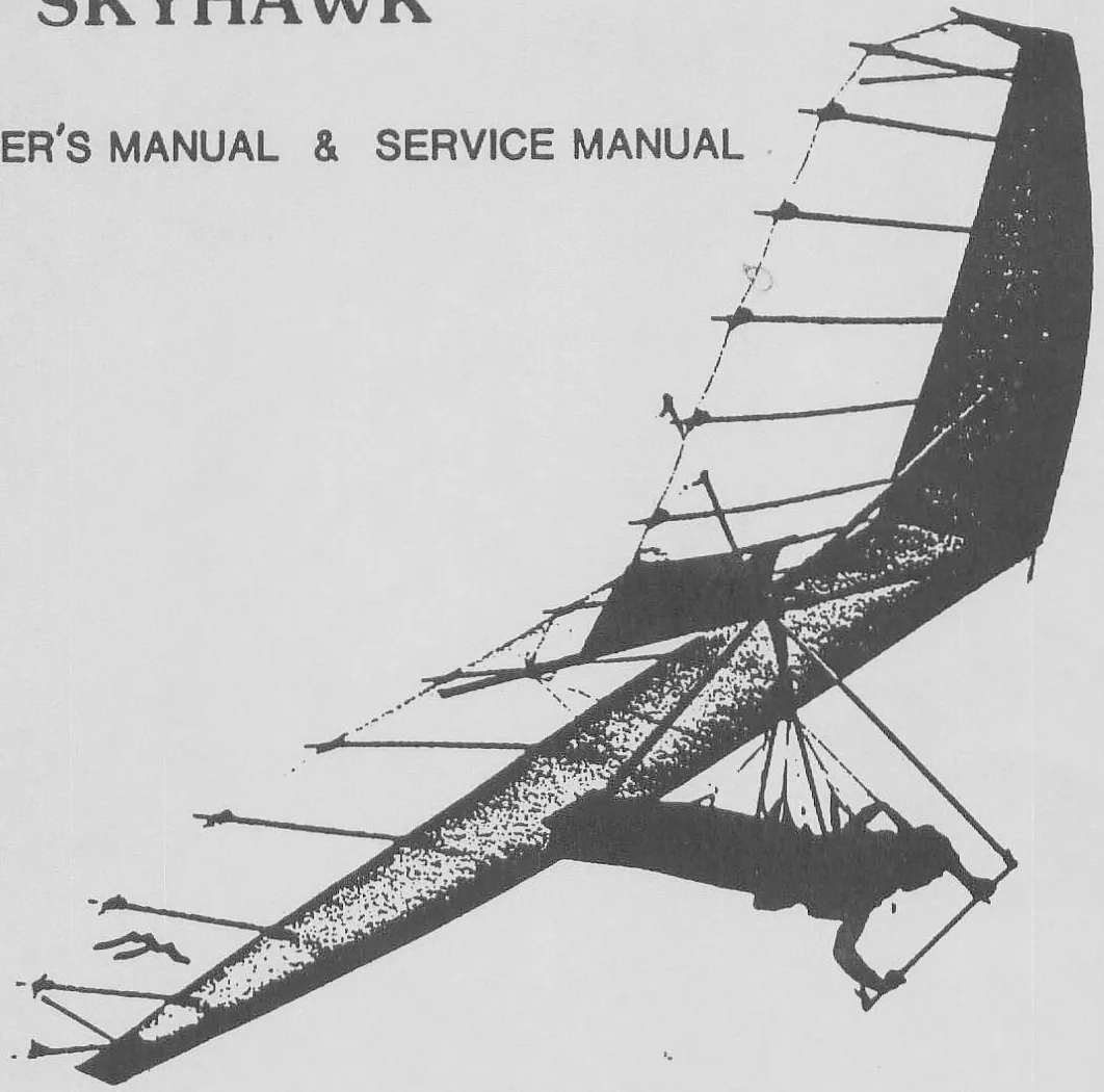
WILLSWING
1208H E. Walnut, Santa Ana, CA 92701 (714) 547-1344/6366
CONTENTS
OWNER SECTION
| INTRODUCTION | 1-1 |
| SPECIFICATIONS | 1-2 |
| TECHNICAL INFORMATION | 1-3 |
| SET-UP PROCEDURES AND PRE-FLIGHT | 1-4 to 1-14 |
| LAUNCHING, FLYING AND LANDING | 1-15 |
| BREAKDOWN PROCEDURES | 1-16 to 1-21 |
| TUNING AND MAINTENANCE | 1-22 to 1-23 |
| A FEW LAST WORDS | 1-24 |
SERVICE SECTION
| INTRODUCTION | 2-2 |
| POST SHIPMENT ASSEMBLY, INSPECTION, TESTFLIGHT AND DELIVERY | 2-2 to 2-4 |
| TUNING | 2-5 to 2-7 |
| MAINTENANCE | 2-8 |
| SERVICE RECORD | 2-9 |
ILLUSTRATIONS 3-1 to 3-16
COMPLIANCE VERIFICATION SPEC. SHEETS
INTRODUCTION
Congratulations! You are now the proud owner of one of the finest footlaunched soaring flex-wings manufactured today. Your WILLS SKYHAWK is the product of an extensive design and development program aimed at optimizing your level of safety and confidence as a pilot, while providing you with a high level of effective soaring performance.
Please read and be sure you thoroughly understand this manual before flying your SKYHAWK. Hang gliding is an extremely demanding sport requiring exceptional levels of attention, judgement, maturity, and self discipline. It is extremely unlikely that you will be able to participate in it safely unless you make a conscious and continual commitment to your own safety. Be sure you are thoroughly familiar with the set up, breakdown, preflight, and maintenance procedures as described in this manual. Make sure you follow all appropriate procedures every time you fly. Never take anything for granted in hang gliding; if you are in doubt about anything, stop and figure it out, consult your manual, your dealer, or Wills Wing, Inc.
We would like to welcome you to the Wills Wing family of pilots, and wish you a safe and enjoyable flying career.
Wills Wing, Inc.
INTRODUCING:
THE WILLS WING SKYHAWK
There is a quiet revolution going on in hang gliding - a return to the roots of the sport, to the concept of hang gliding as an economical, enjoyable form of sport aviation. Wills Wing is leading this revolution, with the world's largest, most professional dealer network, with a unique program of traveling instructor certification seminars, and now, with the new Wills Wing SKYHAWK.
To the experienced recreational soaring pilot, the SKYHAWK offers well coordinated handling, effective sink rate performance comparable to the highest performing flex wings available (at a fraction of the cost), and the confidence in a quality product, engineered and produced by the leading manufacturer of foot launched soaring aircraft in the world.
To the student pilot, the SKYHAWK offers light weight, excellent static balance, smooth predictable control response, easy landings, and slow launching, flying, and landing speeds
The dream of flight is as old as man, and as new as tomorrow's sunrise. The SKYHAWK was engineered to help turn your dreams into reality. It's available ONLY through authorized Wills Wing dealers. See your dealer today.
SKYHAWK Specifications
| MODEL | 168 | 188 |
| AREA | 166 ft\( ^{2} \) | 188 ft\( ^{2} \) |
| SPAN | 30'2" | 32'10" |
| NOSE ANGLE | 115 | 115 |
| ASPECT RATIO | 5.5 | 5.7 |
| PILOT WEIGHT(FOR OPTIMUM PERFORMANCE) | 130-190 1bs | 155-230 1bs |
| GLIDER WEIGHT | 57 1bs. | 64 1bs. |
| PRICE | $1775 | $1775 |
(Inventory colors)

1208H E. Walnut, Santa Ana, CA 92701 (714) 547-1344/6366
SPECIFICATIONS SUBJECT TO CHANGE WITHOUT NOTICE
DEALER INQUIRIES INVITED
If you are a USHGA certified instructor, contact us about our new dealership opportunities.
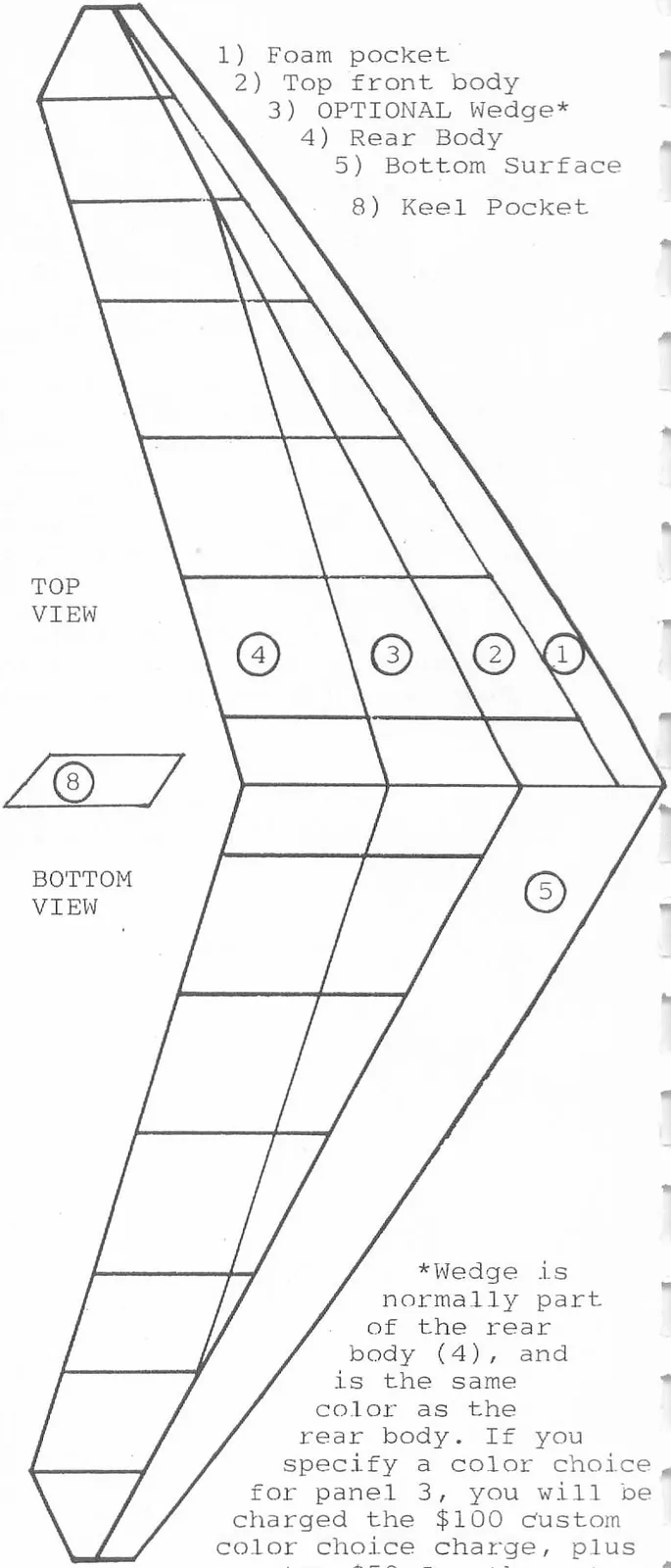
ALL BATTEN POCKETS ARE WHITE
TECHNICAL INFORMATION
The SKYHAWK has been tested and found to comply with the 1984 HGMA Airworthiness Requirements. These standards require for the SKYHAWK:
An ultimate positive load test at the maximum lift angle of attack at a speed of 65 mph.
An ultimate negative 30 degree angle of attack test at a speed of 46 mph.
An ultimate negative 150 degree angle of attack test at a speed of 30 mph.
Pitching moment tests at speeds of 20 mph, 30 mph, and 40 mph which show the glider to be pitch stable over an extended range of angles of attack.
Flight tests which show the glider to be safely controllable and stable over a wide range of normal and abnormal flight modes and conditions.
NOTE: The SKYHAWK was designed for footlaunched soaring flight. It was not designed to be towed, tethered, motorized, nor flown at angles of bank beyond 60 degrees or angles of pitch beyond 30 degrees. Operation in any of these modes may severely compromise your safety, and we strongly recommend against it. Should you decide to fly outside the recommended flight parameters as stated above, please avail yourself of the experience and expertise of those people who are qualified by virtue of their experience in that particular area, and please proceed with extreme caution. Please be advised that Wills Wing can in no way be responsible for the airworthiness, or applicability to any specific purpose of any Wills Wing glider, except as described in the HGMA Airworthiness Standards.
Stall speed of the SKYHAWK at maximum recommended wing loading is 25 mph.
Top speed of the SKYHAWK at minimum recommended wing loading is at least 35 mph.
Recommended Pilot Weight Ranges (Including all equipment):
Skyhawk 188 155 to 230 lbs.
Skyhawk 168 130 to 190 lbs.
Flight operation of the SKYHAWK should be limited to non aerobatic maneuvers, i.e. those in which the pitch angle will not exceed 30 degrees nose up or nose down from the horizon, and in which the bank angle will not exceed 60 degrees. The SKYHAWK will strongly resist spinning, and will tend to recover quickly from a spin once control pressures are relaxed without entering extreme attitudes and without extreme loss of altitude. The SKYHAWK should not be flown at speeds in excess of 46 mph. This speed will generally correspond to a prone pilot position where the pilot has pulled forward such that the basetube lies across the middle of the thigh.
A USHGA pilot proficiency level of II or higher is required to fly the SKYHAWK safely. Flight operation by unqualified pilots may be dangerous and is prohibited.
SKYHAWK SET UP PROCEDURE
NOTE: THE SKYHAWK HAS BEEN DESIGNED TO SET UP QUICKLY AND EASILY AND INCORPORATES A WIDE VARIETY OF NEWLY DESIGNED HARDWARE. USE OF THE SPECIFIC TECHNIQUES DESCRIBED IN THIS MANUAL WILL MAKE THE SET UP AND BREAK DOWN PROCEDURES MUCH EASIER TO PERFORM. PLEASE READ THE MANUAL CAREFULLY AND FOLLOW THE PROCEDURES AS DESCRIBED.
1) Lay the bag on the ground, nose into the wind, zipper up.
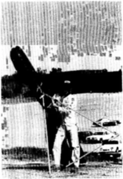
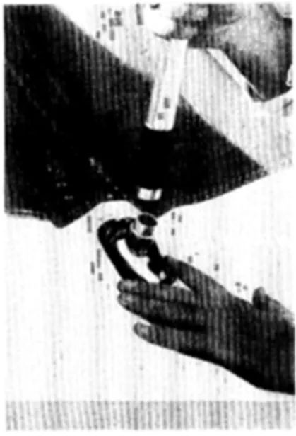
2) Undo the zipper, the velcro securing the control bar, and fold the bar up and forward, allowing the legs to spread as you do so. Attach the bottom nose wires to the nose by sliding the keyhole tang over the shouldered bolt. Secure the rubber keyhole safety to the shouldered bolt. Attach the free end of the base tube to the down tube using the wing nut and safety provided. (fig. 1-4)
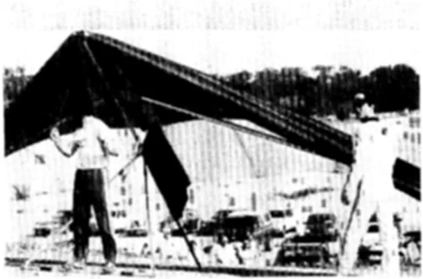
3) Flip the glider upright, and rest it on the control bar, nose into the wind.(fig 5)
4) Remove the bag and all of the velcro straps. Spread the wings most of the way, taking care that the bridles and top side wires are not wrapped around the keel or snagged on the keel hardware.(fig 6) When spreading the wings, you will find it helpful to reach under the leading edge with one hand and lift the crossbar as you spread the leading edge. This will prevent the crossbar from dropping down over the keel and hang up as you try to spread the wings.
5) Make sure that the keel is centered between the leading edges. Lift the kingpost, and fit it over the plug on top of the keel, taking care not to pinch the sail in the process. Check that the bridle cables are not twisted or tangled. (fig 7)
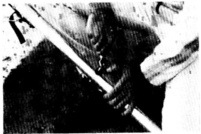
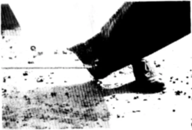
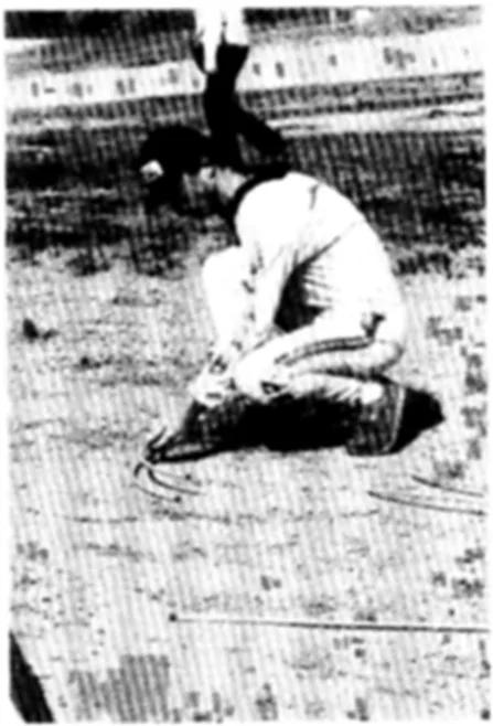
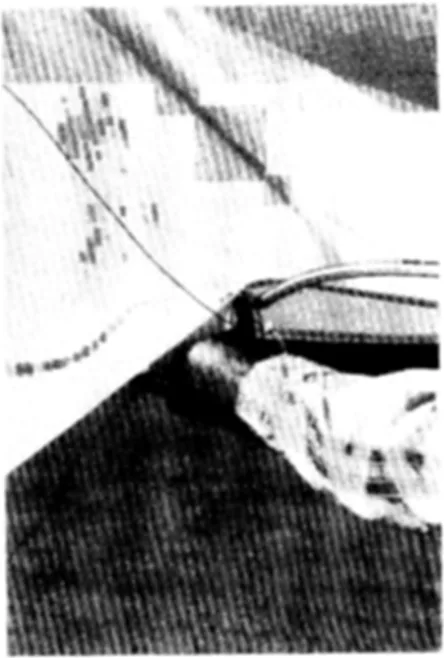
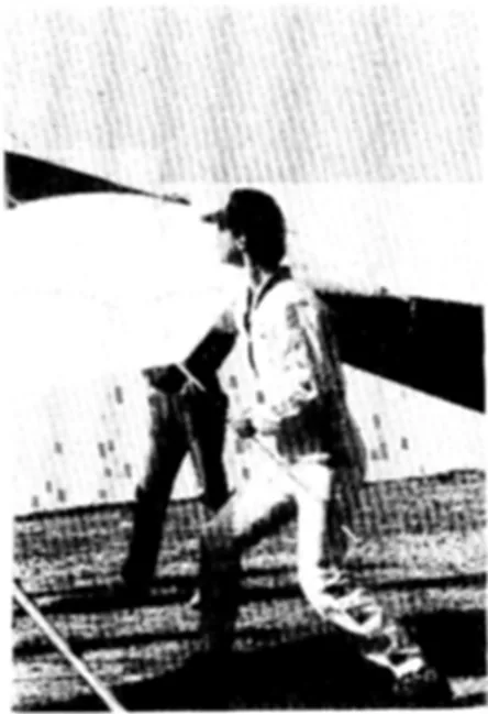
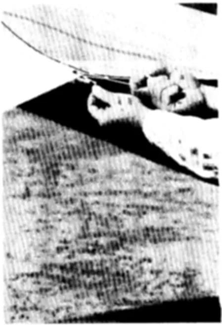
6) Attach the rear kingpost tang to the shouldered bolt on the rear of the keel. BE SURE TO ATTACH THE SAFETY!! (fig 8)
7) Install the washout tips, pushing them firmly into the protruding sleeves until they come up against the clevis pin securing the sleeves in the leading edge. Then rotate the washout tips with your finger on the ball on the underside of the sleeve, until you feel the ball drop into the hole in the washout tip. The tip is now secured in place. NOTE: INSTALLATION OF THE WASHOUT TIPS IS MUCH EASIER IF DONE NOW, BEFORE THE BATTENS ARE INSTALLED.(fig 9-10)
8) Remove the battens from the bag, lay them on the ground, and check them for symmetry, side to side. Correct any that are asymmetric. (See the tuning and maintenance sections of this manual for more information on batten shaping.) Insert the battens into the sail carefully, so as not to de-camber the battens or damage the sail. Order of battens is longest to shortest, from the root to the tip. Half of the battens are marked with tape to make it easier to separate them side to side. By convention, we put the taped battens in the right side, but since they are symmetrical this is not necessary. When inserting the inboard battens, you may find that they become caught behind the crossbar and/or leading edge. If this happens, reach forward with one hand and lift the batten pocket to allow the batten to slide forward. (fig 11-12) After each batten is inserted loop the string over the batten end twice as shown. (fig 13)
NOTE: THE BATTENS MUST BE INSTALLED BEFORE THE CROSSBAR IS TENSIONED. OTHERWISE YOU WILL DECAMBER THE BATTENS AND MAY RUIN THE SAIL.
81
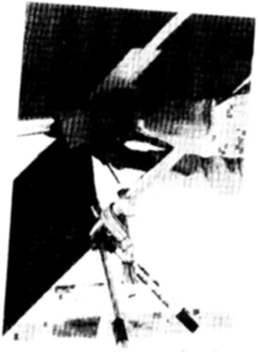
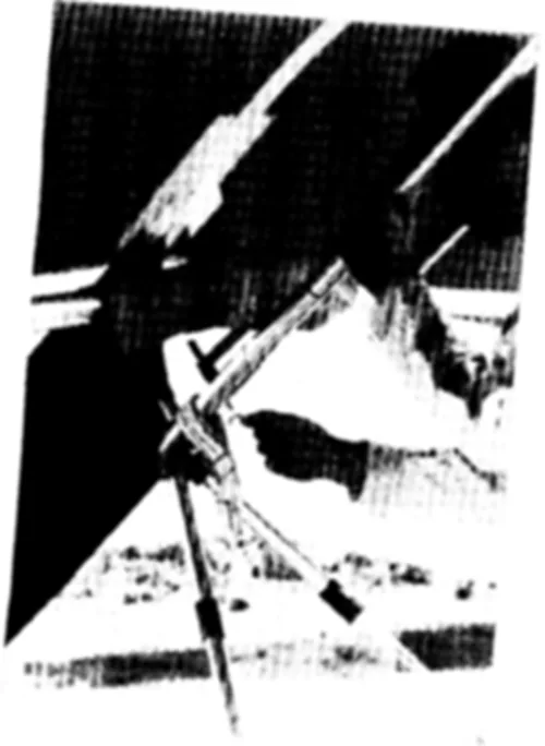
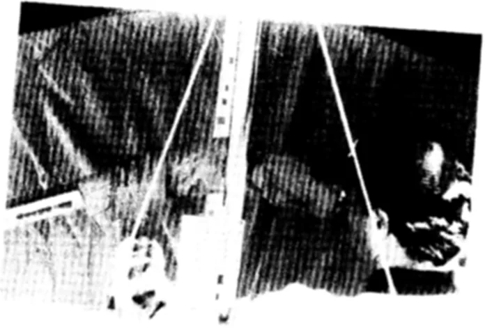

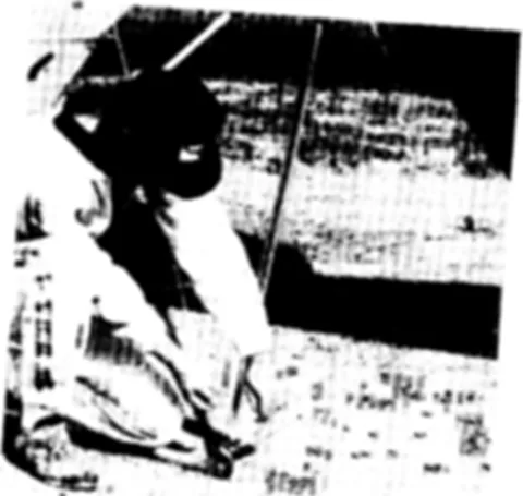
9) Spread the wings all the way and check all wires for twisted thimbles or tangs. NOTE: IF YOU ACCIDENTALLY SET THE GLIDER UP WITH A COCKED THIMBLE AND KINK THE CABLE, YOU MUST REPLACE THAT CABLE IMMEDIATELY OR IT MAY FAIL IN FLIGHT. (fig 14)
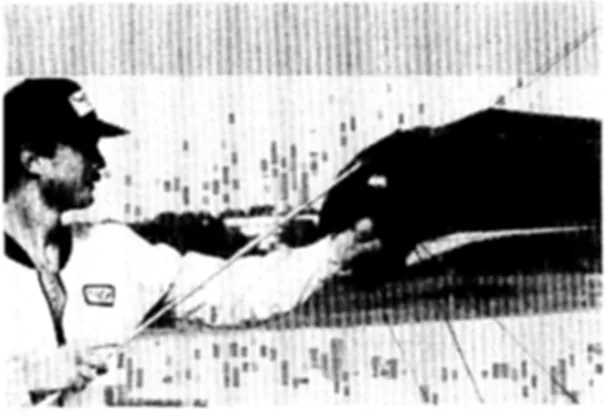
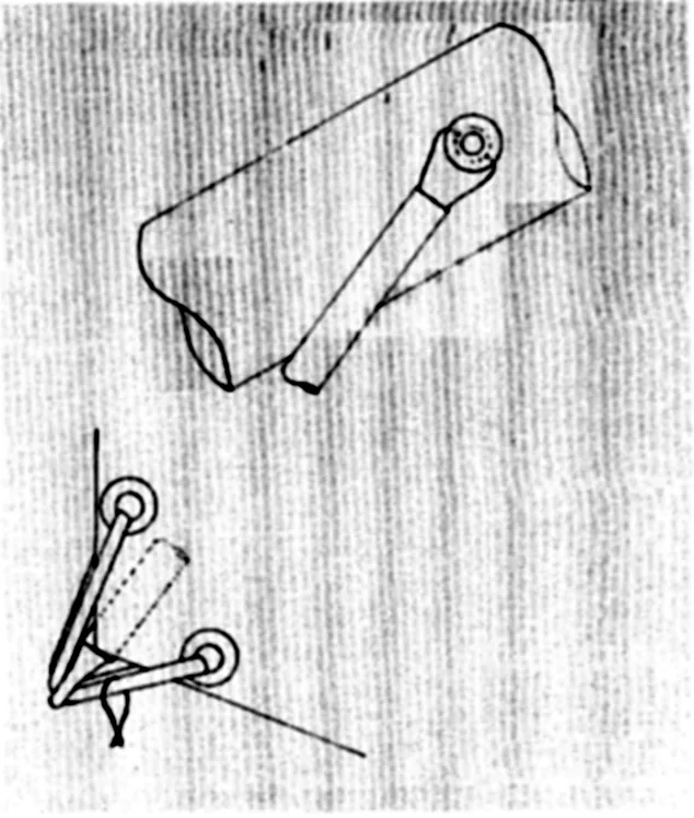
Go to the center of the crossbar, and slide the protective cover bag to one side just far enough to allow you to slide the end of the pivot arm out through the slot in the bottom of the cover bag. Then reposition the bag on the center of the crossbar; the bag must stay over the crossbar center to protect the sail from the crossbar center hardware.(15)Remove the crossbar pivot bolt from the pocket in the cover bag, remove the safety and wingnut from the bolt, and insert the bolt down through the top of the pivot arm. With the pivot arm pointed towards the rear of the glider (swung behind the crossbar) push the crossbar back until you can drop the pivot anchor bolt down through the hole in the keel. Install the wing nut and safety on the bottom of the pivot anchor bolt. (fig 16. 17 and 18). CAUTION: Do not overtighten the wingnut on the pivot bolt as it may restrict the movement of the pivot arm.
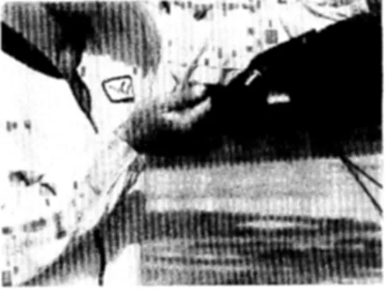
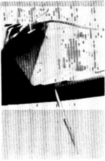
10) Insert the number one battens through the gap in the seam at the rear of the double surface as shown. The forked end of the batten fits over the collar on top of the leading edge. Attach the bungee twice to the rear end of the batten. (Fig 19 and 20).
11) Insert the nose batten as shown and secure the velcro. (fig 21 and 22).
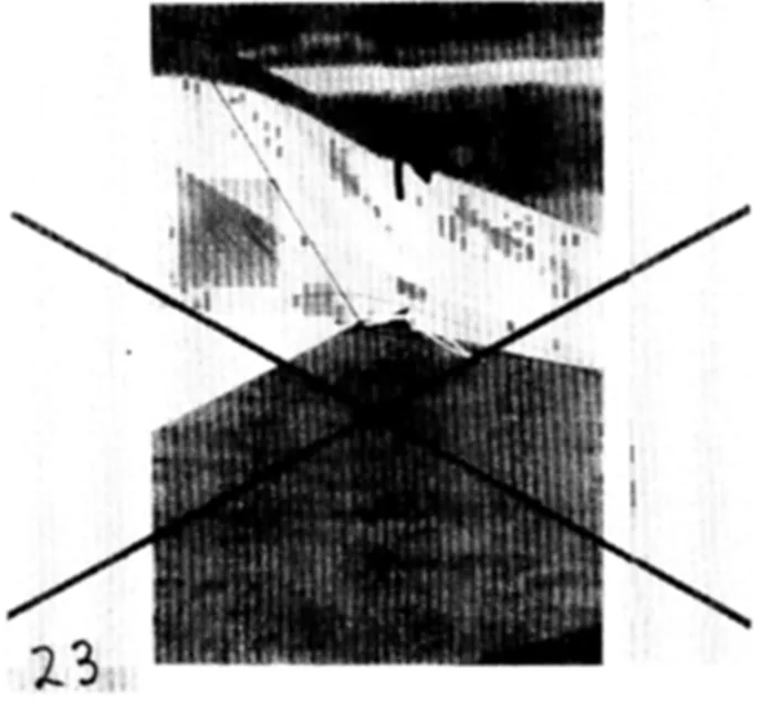
12) Do a complete walk around prefight of the glider. Check every assembly. Make sure there are no twisted wires or thimbles. Make sure that the nose and tail keyhole tangs are properly seated and safetied. Make sure the bridle lines are not tangled, nor looped under an inboard batten. (fig 23) Check each seam in the sail for tears or wear points. Inspect your suspension loop and safety. If you have any doubt about any component, do not fly. Use the checklist below to conduct your preflight:
☐ BATTENS SYMMETRICAL ☐ HANG LOOP SECURED AND OK
☐ BATTENS TENSIONED ☐ KINGPOST ON BASE, SAIL FREE
☐ ALL SAIL STITCHING OK ☐ ALL SAIL GROMMETS OK
BRIDLES OK-NOT TANGLED □ALL NUTS TIGHT ON KEEL CENTER
KEYHOLE SAFETIES SECURE □CONTROL BAR SAFETY RINGS OK (2)
☐ SAIL MOUNT WEBBING ☐ SIDE WIRE NUTS TIGHT ON LEGS SECURE & NOT WORN
☐ SAIL MOUNT CLEVIS PINS ☐ ALL CONTROL BAR NUTS TIGHT SECURE AND SAFETIED
☐ SAIL PLUG ALIGNED & SECURED WITH SCREW
#1 BATTEN SECURE ON STUD SIDE WIRE THIMBLES NOT COCKED
☐ ALL NUTS TIGHT XBAR/L.E. ☐ ALL NUTS SECURE AT NOSE
WASHOUT TIPS SECURE BAG IN PLACE AT XBAR CENTER
☐ NUTS SECURE AT XBAR CNTR ☐ CROSSBAR PIVOT ARM PROPERLY SECURED
☐ NOSE BATTEN INSTALLED AND SECURED
24
LAYING THE GLIDER FLAT
Once you have the glider set up, you can easily lay it flat on the ground:
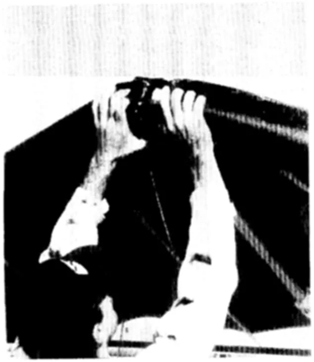
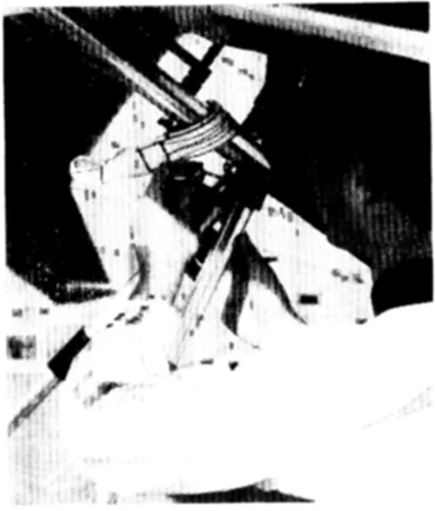
1) Remove the safety from the front bottom nosewire bolt. Place your thumbs against the "T" handle on the keyhole tang and push up on this handle while pulling down on top of the nose as shown. (fig 24) This provides the easiest method for removing the keyhole tang from the nose bolt.
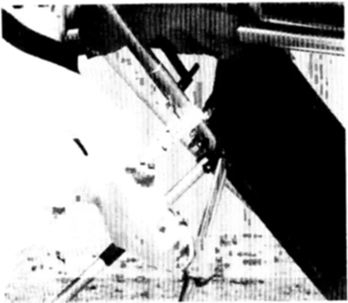
2) Remove the clevis pin and safety from the control bar "U" channel. (fig 25)
3) Lifting the keel, pull the top of the control bar sideways out of the "U" channel, (fig 26), and lay the control bar down.
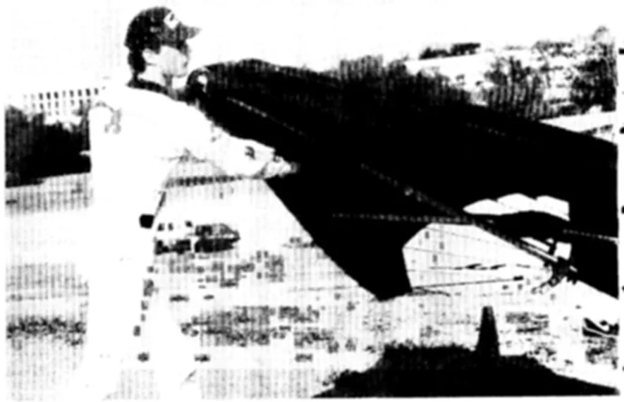
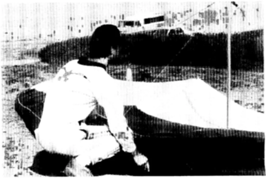
4) Lay the glider flat on the ground (fig 27 and 28). CAUTION: BE SURE TO HAVE THE NOSE POINTED INTO THE WIND WHEN USING THIS PROCEDURE AND BE GENTLE WHEN LAYING THE GLIDER DOWN AND LIFTING IT BACK UP, OTHERWISE YOU MAY BEND OR BREAK THE KEEL. ALSO BE SURE TO DETACH THE CONTROL BAR TOP FROM THE "U" CHANNEL BEFORE LAYING THE GLIDER DOWN!
ALTERNATE SET UP PROCEDURE
In strong or gusty winds, it is best to set up the glider flat on the ground:
1) Begin the set up procedure normally, with the nose into the wind, zipper on the bag facing up. Undo the zipper and undo all the velcros.
2) Assemble the control bar as previously described, and then detach it from the keel as shown in fig 25.
3) Flip the glider over so that it lays nose into the wind, flat on the ground, on top of the assembled control bar.
4) Spread the wings, and follow the rest of the normal set up procedure as previously described, except with the glider laying flat on the ground.
5) When you are ready to fly, lift the nose and attach the control bar and front wires. YOU SHOULD HAVE HELP AT THIS POINT TO STABILIZE THE GLIDER.
6) Proceed with the preflight inspection as previously described. If you don't have someone to hold the nose while you do the preflight, turn the glider carefully so that it is tail down and slightly tail into the wind (mostly crosswind). You should not put the glider nose down or tail down directly into a strong wind.
LAUNCHING THE SKYHAWK
The SKYHAWK has almost neutral static balance. When you hold the glider prior to your take off run, you should have the nose slightly elevated and the wings level. If the wind is more than ten mph or is gusty, you should have at least one wire assistant, on the nose wires. Make sure all signals are clearly understood beforehand. Make sure all spectators are clear. MAKE SURE YOU ARE HOOKED IN and check your position hanging in the control bar. MAKE SURE YOU HAVE PRE-FLIGHTED YOUR HARNESS. Give a good agressive run and ease the bar out for lift-off.
Have a good one!
FLYING THE SKYHAWK
The SKYHAWK has straightforward flight characteristics typical of a defined airfoil flex-wing. Make your first flights from a familiar site in mellow conditions. Give yourself an extra margin of safety in all maneuvers until you are thoroughly familiar with the glider's response characteristics. Note that minimum sink is achieved at a speed substantially faster than minimum controllable airspeed.
LANDING THE SKYHAWK
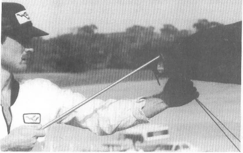
The ideal landing involves a long, straight final approach, with the glider flying directly into the wind, wings level, at a speed well above trim speed. From this point, allow the speed to bleed off gradually, while keeping the wings level and the glider flying straight. Your body position should be upright, leaning slightly forward in your harness, with your hands grasping approximately the middle of the control bar legs, your knees slightly bent, and your feet trailing slightly behind you. Your feet should be no more than a foot or two off the ground as your airspeed approaches minimum sink speed. Your grasp on the bar should be relaxed and sensitive enough that you can feel whether the bar is pulling away from you (you're flying faster than trim speed) or pushing towards you (you're flying slower than trim speed). Unless you are landing with a tail wind (which you should not be doing!) you should not need to slow down much below trim speed before you flare. At the point where letting the bar out further does not allow you to slow down anymore and maintain a horizontal glide, it is time to flare. Push out strongly and quickly on the bar to the full extension of your arms, and allow your feet to swing beneath you.
You must remember that the timing of the flare relates to your AIRSPEED, not your groundspeed. When landing in a 15 mph headwind, for example, you will find that no flare is necessary, since you can slow the glider down to zero groundspeed prior to the need to flare. In no wind conditions, your groundspeed will still be substantial when the time to flare arrives. If you are judging the timing of the flare by
62
28
L2
9c your groundspeed, you will probably flare too late and stumble forward in no wind landings, while you may flare too early or when it is unnecessary in strong wind landings.
SKYHAWK BREAKDOWN
Breakdown of the SKYHAWK is simply the reverse of the set up procedure.
1) Remove the nose batten first. (fig 26)
2) Detach the top rear wire at the rear of the keel. (fig 27)
3) Remove the crossbar pivot bolt and let the crossbar swing forward and rest against the keel. (fig 28)
4) Slide the crossbar cover bag to one side allowing the pivot arm to slide back into the bag. Then reposition the cover bag over the center of the crossbar.
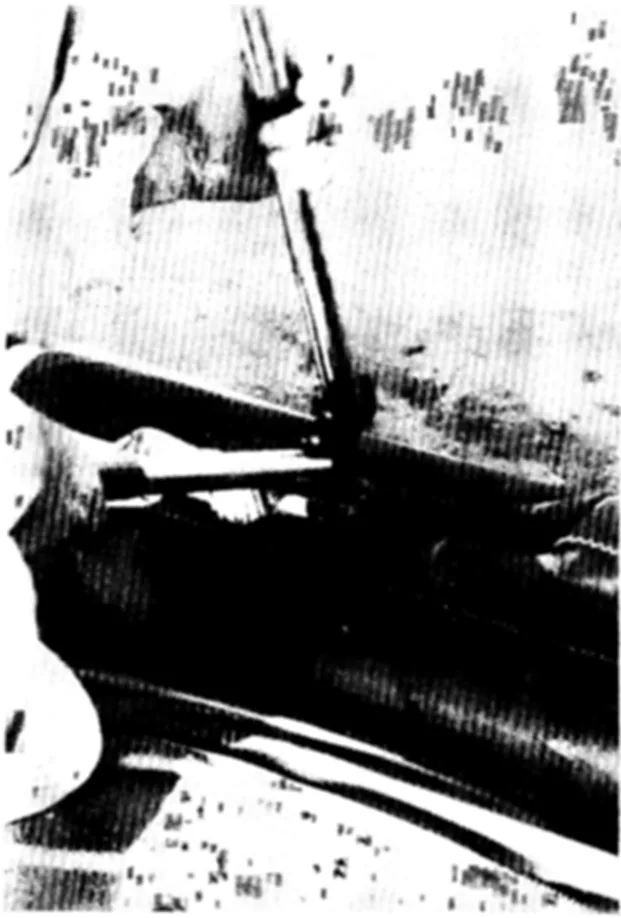
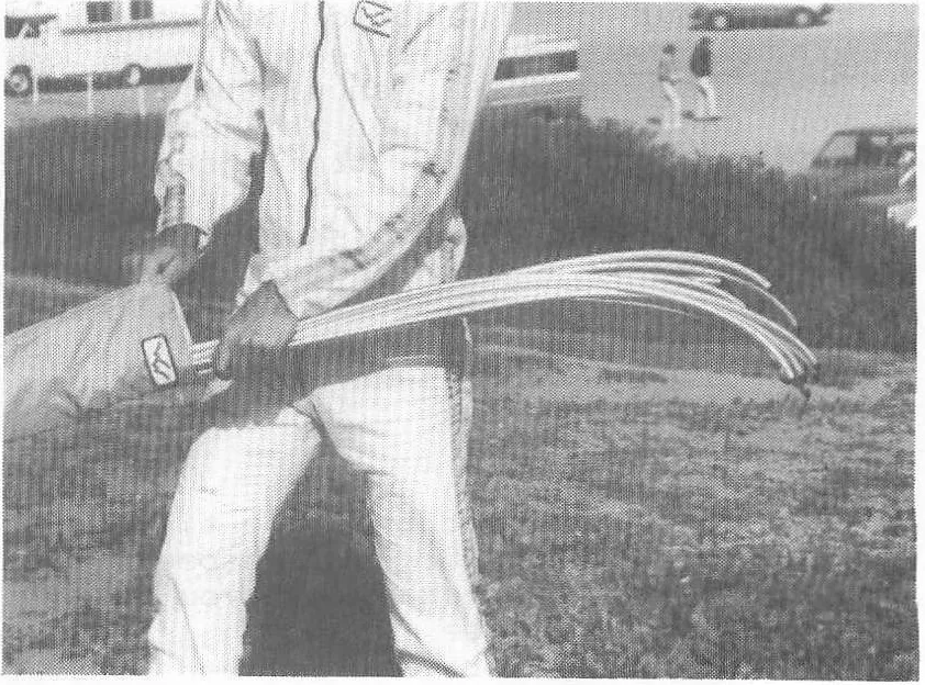
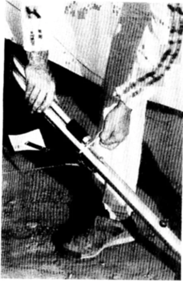
5) Pull the wings in slightly and remove all the battens. Place the curved battens carefully together (fig 29) and stow them in the batten bag. The straight number one battens will be rolled up in the sail.
30
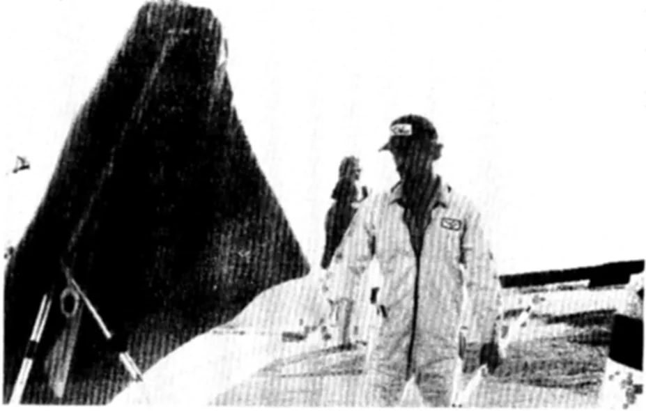
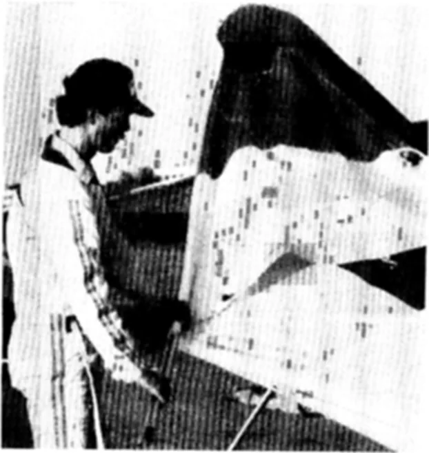
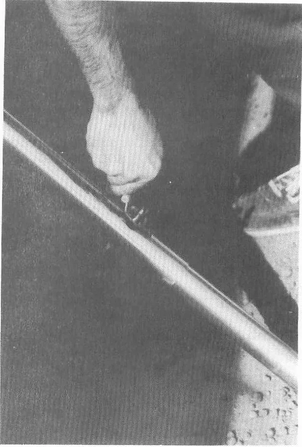
6) Remove the kingpost from the base, and slide it back into the keel pocket securing it under the bungee retainer. (fig 30)
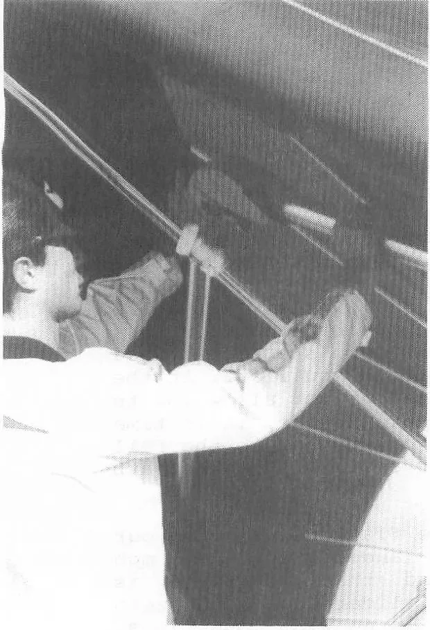
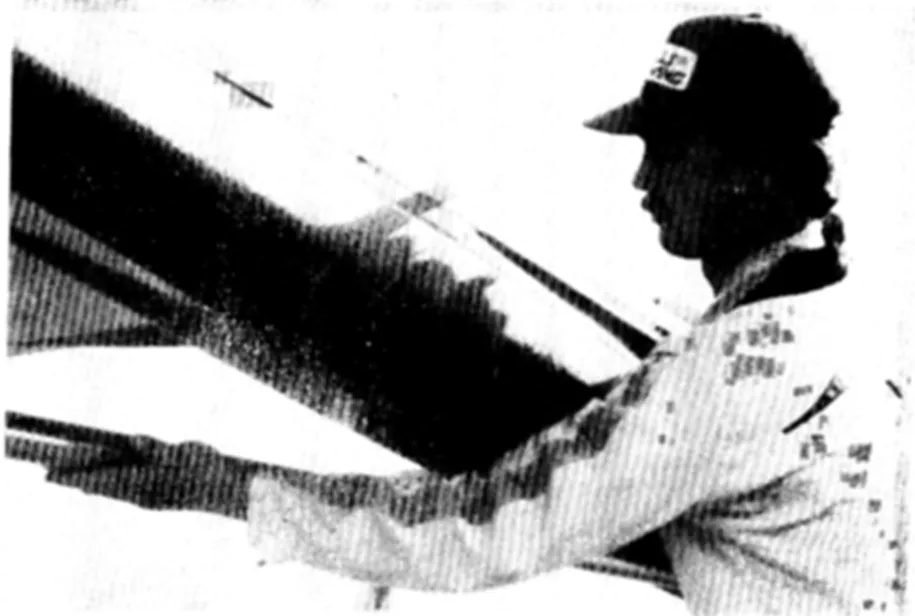
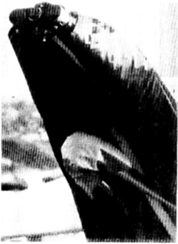
7) Remove the washout tips. Place one hand under the crossbar, and lift it as you fold in the wing. (fig 3/) PROPER EXECUTION OF THIS TECHNIQUE IS VERY IMPORTANT; OTHERWISE THE CROSSBAR WILL TEND TO DROP BELOW THE KEEL AND LEADING EDGES (FIG 32). IF THIS HAPPENS, THE LEADING EDGE/CROSSBAR JUNCTION PLATE MAY BEND OR BREAK, AND THE CROSSBAR MAY BE PARTIALLY CRUSHED AND WEAKENED. Take care not to pinch your hand between the leading edge and crossbar when folding in the wing. After carefully folding in both wings and checking to see that the crossbar is properly located above the keel and leading edges, pull the sail out over the top of the leading edges on each side. (fig 33).
8) Roll the washout tips and number one battens up in the sail as shown. (fig 34)
9) Place one velcro strap around the glider just aft of the leading edge/crossbar junction. Secure the velcro strap that is attached to the front keel. MAKE SURE THIS STRAP PASSES OVER THE TOP OF THE KEEL AND SUPPORTS THE LEADING EDGES ABOVE THE CONTROL BAR TOP "E" BRACKET. (See diagram)
35
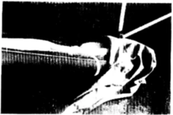
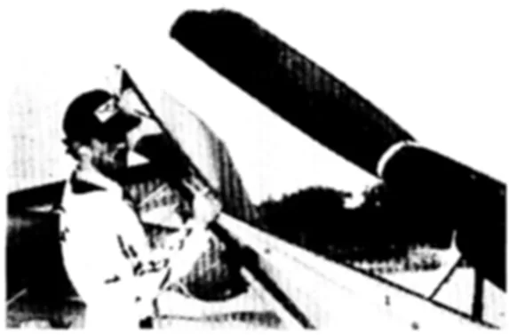
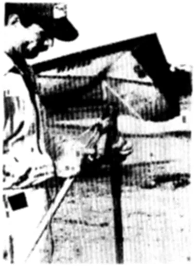
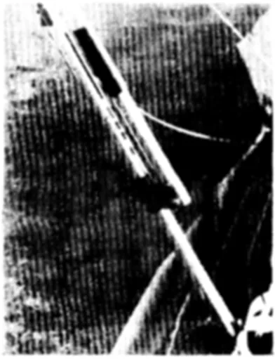
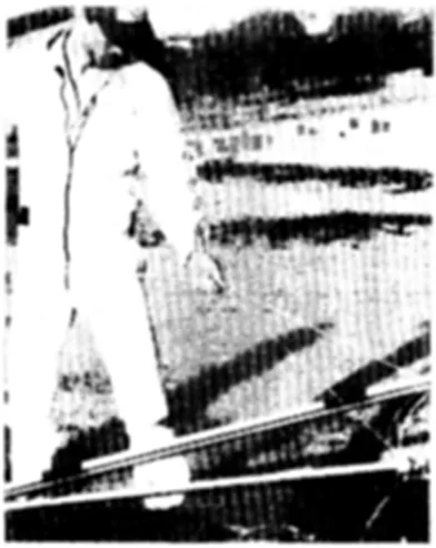
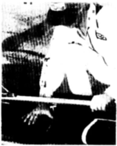
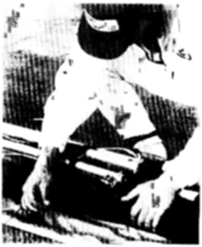
10) Install the protective rubber caps over the washout studs as shown. (fig 35) Install the third velcro around the leading edges as this point, taking care that the sail is not pinched between the leading edges. Slide the glider bag on the end of the glider as shown. (fig 36).
11) Place the rest of the glider bag over the glider. (fig 37) Lay the glider on its side and disconnect the leg from the "U" bracket as shown. (fig 38)
12) Fold the base tube against the other leg as shown, securing the "U" bracket over the rubber protector. (fig 39)
13) Detach the nose wires and allow the bar to fold back and together. (fig 40)
14) Slide one half of the pad under the keel as shown. (fig 41) Fold the other half of the pad over the keel, lay the control bar down against the pad, and secure the velcro as shown. (fig 42) Zip up the bag.
SKYHAWK TUNING
There are a number of adjustments which can be made on your glider for tuning purposes. You should be very careful when changing the tuning of your glider. Make sure you know what to expect before you make any tuning changes. Read the section in the service section of this manual on tuning and make sure you understand and follow the instructions carefully. Make all tuning changes in small increments, and test fly the glider from a familiar site in mellow conditions following each change.
SKYHAWK MAINTENANCE
You should inspect your battens for left/right symmetry before each flight, and correct any asymmetry. You should true them to the pattern periodically. See the section on batten maintenance in the service section of this manual for further information.
You should periodically inspect your bridles in flight for proper adjustment. See the service section of this manual for further information.
Your SKYHAWK should have a complete maintenance inspection every six months or 30 hours of airtime, whichever comes sooner, or at any time that you have reason to believe that any component may have been damaged.
Maintenance and service should be performed by your Wills Wing dealer.
MINIMUM SERVICE SCHEDULE
EVERY SIX MONTHS
Complete maintenance inspection of sail and airframe (requires removal of sail from frame.) Replace any parts that show signs of wear. Have any tears or wear points in sail repaired by a professional sail maker.
EVERY YEAR
Replace hang loops, harness suspension lines, bridle cables, all airframe support cables.
SPECIAL CIRCUMSTANCES
Any time you suffer a crash or hard landing you should thoroughly inspect your glider and replace any parts that are bent or broken. Inpspect the sail carefully for tears, especially along the trailing edge, at the rear leading edge attachment points, and at the kingpost cut-out. Have any sail damage repaired by a professional sail maker.
Even a simple ground handling mishap may cause concealed damage, such as bent battens, which could severely affect your glider's flight characteristics. If your glider flips over in the wind, or something similar happens, you should breakdown far enough to remove and inspect your battens, and perform a careful preflight after re-assembly.
It is possible to bend a leading edge on a hard landing and not be able to discover the damage without removing the sail from the frame. The flight characteristics of a glider with a bent leading edge may not be noticeably different, while the safety of the glider may be significantly compromised.
If your glider is ever exposed to salt water you must rinse it thoroughly with fresh water, including the insides of all tubes. This will require the removal of all end caps. After rinsing, or any time your glider gets wet, you should dry it thoroughly, remove the endcaps from all tubes, and swab the insides of the tubes with an oil dampened rag.
Anytime your sail is rolled up wet, there is a chance that the colors in the cloth or webbing will bleed and run. There is also the possibility of material degradation due to mildew. If you have to roll your sail up wet, roll it loosely, and open it up and dry it out as soon as possible.
Your sail should never be washed in anything other than fresh water, as any soap or detergent will likely degrade the cloth and may adversely affect the flying characteristics.
You should not apply Armorall, or any other preservative substance to your sail. These substances prevent seamstick tape from adhering to the material and make sail repair almost impossible.
You should avoid unnecessary exposure of your sail, your hang loop, or any of your harness equipment to ultraviolet light (sunlight), heat, acid (lemonade, urine, etc.) or any other condition or substance which may cause premature material degradation. Don't set your glider up until you are ready to fly, and break it down when you are through flying.
With proper care and maintenance, your glider will retain for some years a high level of airworthiness. The SKYHAWK was tested and found to comply with the 1984 HGMA Airworthiness Standards, which represent the best accumulated knowledge of what constitutes airworthiness in a hang glider. There is much that we still do not know, such as what is the effective lifetime for a hang glider before material fatigue and degradation compromise the glider's airworthiness. We do know that there are forces in nature which can severely compromise your safety regardless of the quality of design or condition of the aircraft you are operating. Your safety is ultimately your responsibility. We strongly recommend that you fly conservatively, both in your choice of the the conditions in which you fly and the safety margins you allow in the manuevers you attempt. We recommend that you fly only with a harness that has been tested for strength by the manufacturer, and that you always fly with an emergency parachute system. Our experience has shown us that pilots who fail to follow these recommendations are often killed or severely injured in accidents that could easily have been prevented.
CAR TOP MOUNTING
Your SKYHAWK should be mounted on your rack with the control bar bracket (zipper on the bag) facing upwards, and the flag at the rear. Your rack should have at least three support points, spanning at least 13' of the glider. These should be padded and at least 4" wide to distribute the load. You should be careful when securing your battens that you do not bend them.
A FEW LAST WORDS
Your Wills Wing SKYHAWK is a sophisticated high performance glider that will give you years of safe and enjoyable soaring, provided that you treat it properly and always maintain a healthy respect for the demands and potential dangers of flying. Please remember that aviation is always potentially dangerous, and that your safety depends on you. You are reminded that this glider is not covered by product liability insurance, and that you fly a hang glider at your own risk.
See you in the sky!
Wills Wing, Inc.
INTRODUCTION
This section of the manual is intended for the use of Wills Wing dealers performing service on the glider. THIS MANUAL ASSUMES A HIGH DEGREE OF FAMILIARITY WITH HANG GLIDER SERVICE PROCEDURES, THE USE OF APPROPRIATE TOOLS, ETC. WE STRONGLY RECOMMEND THAT ALL SERVICE PROCEDURES BE PERFORMED BY A QUALIFIED WILLS WING DEALER. We know of several incidents of serious accidents which were caused by improper assembly of glider components during service procedures done by pilots unfamiliar with general practices of glider design and assembly. When doing service work on a hang glider, please be absolutely sure you know what you are doing; someone's life will depend on it. There are numerous photographs and diagrams in this manual to help you understand the proper assembly of the glider. If you have any questions after studying the manual, please contact Wills Wing.
POST SHIPMENT ASSEMBLY
Part of your required service as a Wills Wing dealer is to unpack, assemble, inspect and test fly each glider before you deliver it to the customer. The following instructions cover this pre-delivery procedure.
If the glider has been shipped full length, it requires no assembly other than the normal set up procedure described earlier in the owner section of this manual. Please refer to that section.
If the glider has been broken down for shipment, the rear leading edges will have been removed, and will need to be re-installed.
1) Remove the glider and parts from the shipping tube, unzip the bag, and spread the leading edges slightly. The rear leading edges should be marked to indicate right and left. Remember that with the glider lying on its back, the right leading edge will be on your left, as you look from the tail of the glider. The assembly of the rear leading edge to the front is secured by a clevis pin. When the leading edge is properly installed, the plug in tip sleeve will point up and in, at an angle of about 30 degrees from the horizontal. (With the glider upside down on the floor or table, the sleeves will point in and down at 30 degrees.) If improperly installed, the sleeve will point either outwards, which would make it impossible to assemble the glider, or in and down at 30 degrees from the horizontal, which would put 30 degrees of negative twist in the tip and make the glider extremely unsafe to fly. Once again, please note that when the glider is lying on its back (when the zipper on the bag is up) the washout tip sleeves will point "down" and in when properly installed, since the glider is upside down.
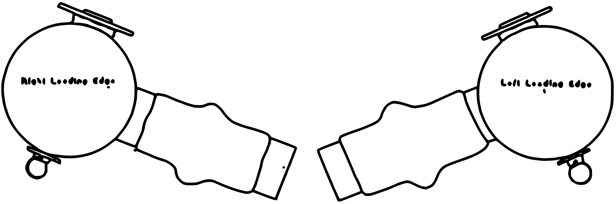
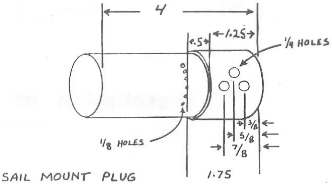
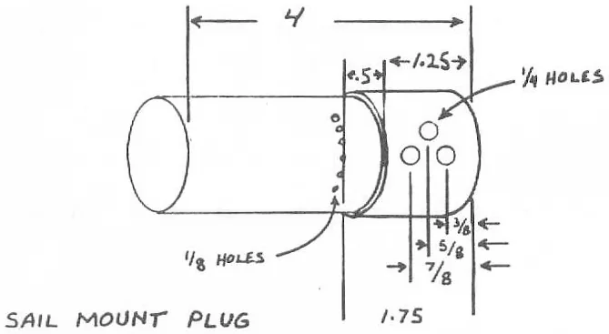
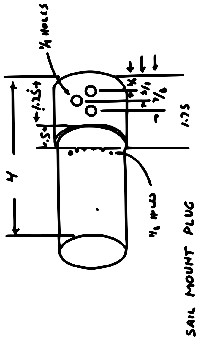
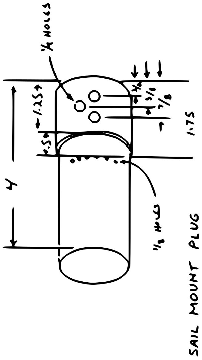
2) Once the leading edges are properly installed and secured with the clevis pin and safety, the sail may be mounted at the rear. Refer to the diagram for the proper installation of the clevis pin, washers and safety. NOTE THAT THE SAIL IS MOUNTED TO THE BOTTOM OF THE LEADING EDGE. The proper orientation of the sail mount plug will have the sail mount clevis pin aligned as shown to the washout sleeve, unless the sail mount plug has been rotated to correct for a turn. In this case there should be only a slight variation from the normal orientation.
ANYTIME YOU ARE MOUNTING OR DISMOUNTING THE SAIL AT THE REAR LEADING EDGE, CHECK THE CONDITION OF THE WEBBING AND GROMMET WHICH SECURE THE SAIL TO THE CLEVIS PIN. IF THE WEBBING IS TORN OR THE GROMMET IS LOOSE, HAVE A SAILMAKER REPLACE THEM, MAKING SURE THAT THE REPLACEMENT GROMMET ENDS UP IN EXACTLY THE SAME POSITION. ALSO CHECK TO SEE THAT THE SAIL MOUNT PLUG IS PROPERLY ALIGNED AND SECURED WITH A SET SCREW.
3) When mounting the sail at the rear of the leading edge, you may find it difficult to stretch the sail back far enough to install the clevis pin. If so, you can dismount the sail at the nose. If you do dismount the sail at the nose, you should remount it immediately after mounting the rear. Otherwise the sail will slide rearward on the frame at the nose, and when you spread the leading edges during set-up, you will tear the sail. You should never fly the glider without the sail properly mounted at the nose.
SET UP, INPSECTION AND TEST FLIGHT
Following removal of the glider from the tube and installation of the leading edges (if necessary) set up the glider according to the instructions in the owner section of this manual. Before inserting the battens, check them against the pattern and recamber any that may have been altered in shipping.
When installing the battens, check that the batten strings are properly adjusted, and re-adjust any that require it. Proper adjustment of the strings will allow you to pull the string just past, but not more than 1/4" to 3/8" past the end of the batten before the pain in your finger becomes severe. Root batten strings should be relatively looser, and outboard (1 through 4) batten strings should be tighter. If the strings are too loose on the outboard battens, the sail may flutter at the trailing edge. If the strings are too tight, the batten pockets may wear through prematurely in the front. If the root strings are too tight, the handling may be unnecessarily stiff, while if they are too loose there may be excessive wrinkles in the sail body.
Following set-up, perform a complete pre-flight inspection of the glider as described in the owner section of this manual. Your attitude during this inspection should be to assume that the glider was improperly made and assembled, and not test flown. IN OTHER WORDS, DON'T TAKE ANYTHING FOR GRANTED. DON'T ASSUME THAT THE GLIDER IS PROPERLY PUT TOGETHER JUST BECAUSE IT CAME FROM THE FACTORY. At this point in time it becomes your responsibility to make sure that the glider you deliver to your customer is right, in every respect. Check to see that the factory test fly sticker is signed; if it is not, give us a call.
After you have inspected the glider, the next step is the test flight. You should first familiarize yourself with the procedures on test flying as outlined in the Wills Wing Dealer Test Fly Manual. You should fly the glider from a familiar site in mellow conditions. During the test flight, perform the following maneuvers:
1) Multiple 360 degree turns at shallow bank angles in both directions. This is the best way to detect a turn in the glider; it will feel mildly roll stable to one side and mildly roll unstable to the other. Properly tuned, the glider will be essentially roll neutral to slightly roll stable, and will be equally so to both sides. At this time, also check for proper speed trim.
2) Low speed roll initiation from wings level. This is a test for adverse yaw; the tendency of a glider to resist rolling and yaw in the wrong direction at low speeds. Some degree of adverse yaw may be present at very low speeds, but from trim speed on up, the glider should roll in smoothly with good coordination, and should not require you to pull in on the bar prior to roll initiation.
3) Sustained, pilot full forward dives. The bar pressure in a dive should be substantial, and it should be smooth, progressive and consistent. If it is not, carefully check the bridle settings, the alignment of the sail mount plugs, and the batten camber.
If the glider exhibits any improper flight characteristics, refer to the tuning section of this manual and try to correct the problem. Fly the glider between each adjustment to check on your progress. Do not deliver a glider until it has exhibited in flight the proper flying characteristics. If you have a problem you cannot solve, please contact Wills Wing. After you are satisfied that the glider flies properly, initial and date the appropriate box on the red advisory placard on the bottom of the keel.
The final steps in your glider delivery procedure are to review the set-up, breakdown, and transport procedures, as well as the owner's manual with your customer. Fill out the glider delivery checklist, have your customer initial it, and send it in. Deliver the team cap, spare parts kit, and batten diagram. Also, please encourage your customer to send in his customer response form.
TUNING
In this section we will cover the effects of all the tuning
BATTENS
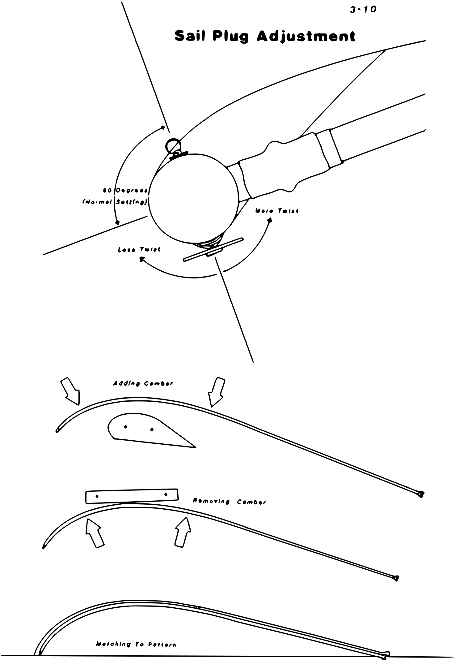
The battens will need to be trued to the pattern from time to time. Repeated installation and removal will tend to de-camber the battens. Hard landing and nose-ins may bend the tip battens or induce reflex into the #3 and #4 battens. (Note:Battens are numbered from the tip inboard. The reason for this is that on scaled sizes the outboard (#1, #2 etc.) battens will be the same batten, while a smaller glider may not have a #7 batten.) Small variations in batten camber will not have a significant effect on flight characteristics. Excessive camber in the battens will usually make the glider trim faster, have less bar pressure in a dive and be less pitch stable, and be stiffer and slower to roll. Too little camber will reduce the performance of the glider. Battens which are asymmetric from left to right will tend to induce a turn in the glider. Note that the number one batten is straight.
The best way to true battens is in the shop on a flat table, using a radiused template as shown. Try to avoid putting sharp kinks in the batten. Unlike structural frame members, battens may be bent and re-bent repeatedly without causing any safety hazard. However, you may find it easier to replace a badly bent batten than to re-true it. When re-shaping a batten the material will tend to spring back after it is bent, so some practice is required to arrive at the proper final bend. We recommend against truing battens to the pattern outside the shop. In the field a bent batten can be trued to it's corresponding batten from the other side. As long as the battens are symmetrical and close to the proper shape, the glider will fly normally. When truing the battens to the pattern, line up each end of the batten underneath the line on the pattern, and check for the deviation along the batten as described on the pattern.
KEEL POCKET RESTRAINING STRAP
This strap, which mounts the keel pocket to the rear of the keel, determines the ability of the inboard section of the wing to take camber. If it is too tight, the camber will be restricted, and handling and performance will suffer. To check the adjustment, rest the glider on its tail, stand on the base tube, and push up hard on the sail at the center, just behind the double surface. If there are diagonal wrinkles in the keel pocket, the strap is too tight and is restraining the sail improperly. If there is excessive slack in the keel pocket behind the trailing edge, or in the strap, the strap is too loose.
REFLEX SUPPORT BRIDLES
The proper adjustment for the reflex bridles is just slack in normal flight. The dimensions listed on the compliance verification specification sheet in the rear of this manual give you the normal measurements. However, the "just slack" criterion is the determining factor. This is best determined by flying the glider and sighting the shadow of the bridles on the sail. They should be perceptibly slack, but not more than just slack. Be sure to distinguish between the curved shadow of a straight bridle on the curved surface of the sail, and the shadow of a bridle line which is curved because it is hanging slightly slack. Slack bridles will wiggle when you shake the control bar. If the bridles are too tight, the handling of the glider will be seriously degraded. If they are too loose, the glider will not have the level of pitch stability for which it was designed and certified, and may not be safe. LOOSENING THE BRIDLES BEYOND THE PROPER ADJUSTMENT WILL NOT IMPROVE EITHER HANDLING OR PERFORMANCE.
FRONT TO REAR WIRE LOOP LENGTH ADJUSTMENT
SEE ADDENDUM IN REAR
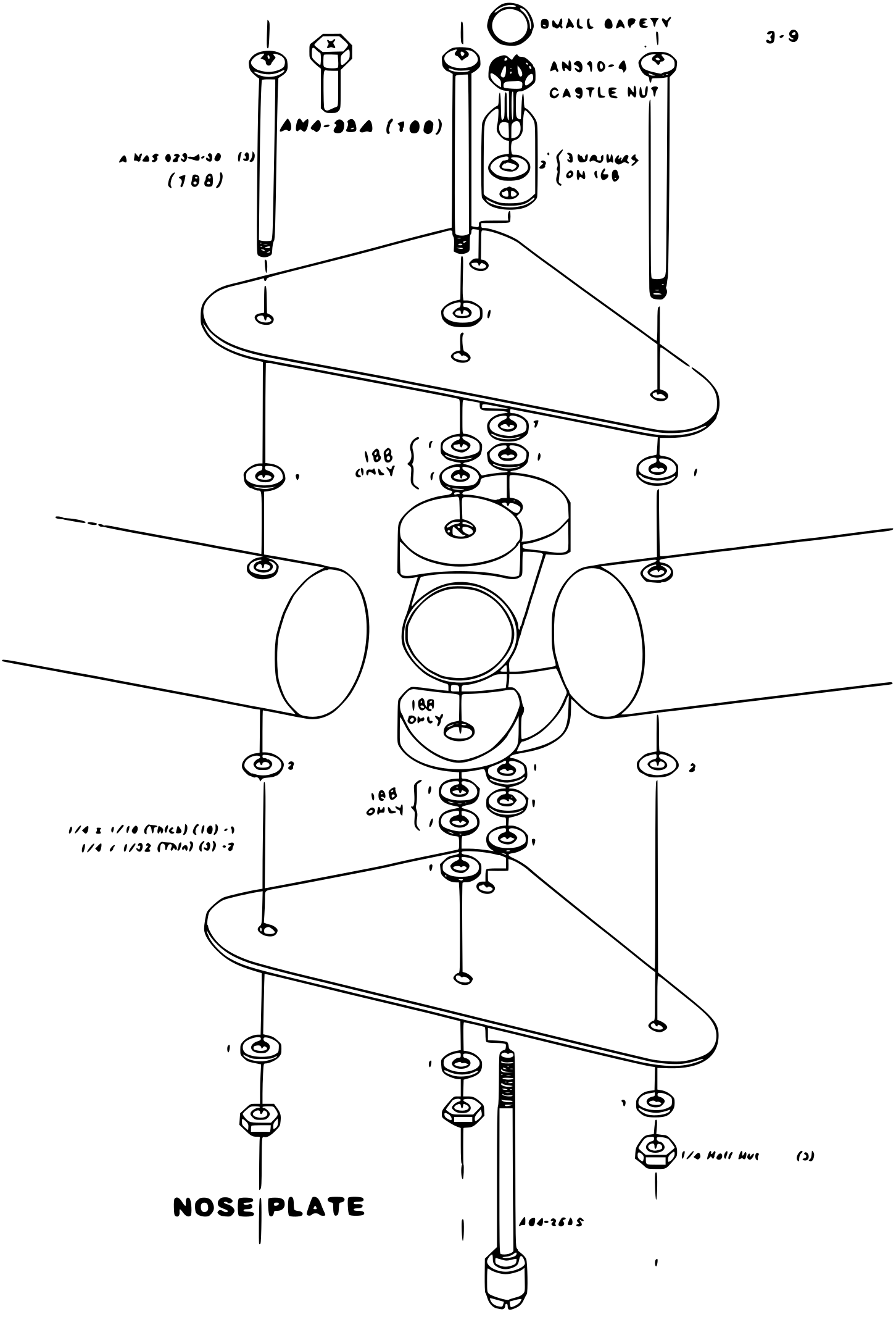
There are washers stacked underneath some of the nuts and bolts that attach the wires to the keel. Redistribution of one or more of these washers will allow for some adjustment of the tension in the front to rear wire loop. This loop should be snug, but not so tight that you have difficulty attaching or removing the keyhole tang from the top rear wire bolt. Following the removal or addition of washers you should install a new nylock nut, and check to see that at least one or more threads protrude from the nylon in the nut after installation. If you cannot achieve the desired adjustment in this manner, order a longer or shorter top rear wire from the factory.
LEADING EDGE SAIL TENSION
The leading edge sail mount plug has three holes for the adjustment of leading edge sail tension. The provision for tensioning the sail tighter than normal is primarily intended to retention older sails which may have stretched along the leading edge. Tightening the sail will tend to slightly improve performance, but tends to make the glider stiffer and slower to turn, and to increase the tendency for adverse yaw. Loosening the leading edge sail tension is usually the single most effective way to improve the handling of a stiff, slow rolling glider. (Check first to see that all other adjustments are properly set.) However, loosening the sail beyond a certain point will make handling worse rather than better. When remounting the sail to a different hole in the plug, make sure to rotate the plug appropriately so as to maintain the proper amount of twist in the tip. Also make sure to secure the plug with the set screw following any such adjustments. (See the appropriate diagrams in the back of this section.)
LEADING EDGE SAIL MOUNT PLUG
This plug can be rotated to change the effective twist in the wing tip. Adjusting this twist is the most effective way to correct for a tendency of the glider to turn to one side. The normal adjustment results in the sail mount clevis pin being almost parallel (see diagram) to the washout tip sleeve. Rotating the plug so as to twist the trailing edge up (Clockwise for the right tip) will make the glider turn towards that wing, while rotating the plug so as to reduce twist in that wing will make the glider turn away from that wing. When adjusting for a turn, you may find that decreasing the twist in one wing is more effective than increasing the twist in the other wing. Whenever changing this adjustment, do so in small increments, and make sure to re-secure the plug with the set screw. Rotating both tips up will tend to reduce the trim speed, increase the pitch bar pressure, and make the glider more roll stable. You should not rotate BOTH tips down below the point where the clevis pins are parallel to the washout tip sleeves, nor should you rotate either tip down to the point where there is less than 1" clearance between the sail and the end of the washout tip in flight at trim speed. You should not have to rotate either tip more than one notch away from the stock adjustment. If the glider cannot be properly trimmed without doing so, call the factory.
SEE ADDENDUM IN REAR
MAINTENANCE
Schedule:
Every Six Months: Complete maintenance inspection of sail and airframe. Remove sail from frame, inspect sail for tears and wear points and repair as necessary. Insect frame for bent, dinged, or gouged members. Replace any compression members (crossbar, control bar leg, kingpost) that show damage anywhere in the middle 3/4ths of the length. Replace any member that is severely damaged at any point. Replace any leading edge that shows damage not confined to within two feet of the nose or tail. Check the leading edge nose bolt bushings for wear or oblong holes. Replace any cable that shows any wear or damage. Replace any bent bolts, and all nylock nuts removed during disassembly. Replace hang loop if it shows any wear. Carefully inspect the sail mounting webbing loops at the rear of the leading edge; have these replaced by a sail maker if they show any signs of wear. Replace any safety rings that are bent or deformed. Replace the safeties on the keyhole tangs, and the rubber sleeves on the washout tip sleeves. Inspect the batten retaining strings and replace or adjust if necessary. Inspect all tubes, bolts, and cables for corrosion.
Every Year: Perform the six months service and, in addition, replace all airframe support cables. Also replace the bridle cables. Replace the hang loop. Advise the customer to replace all main suspension lines on the harness.
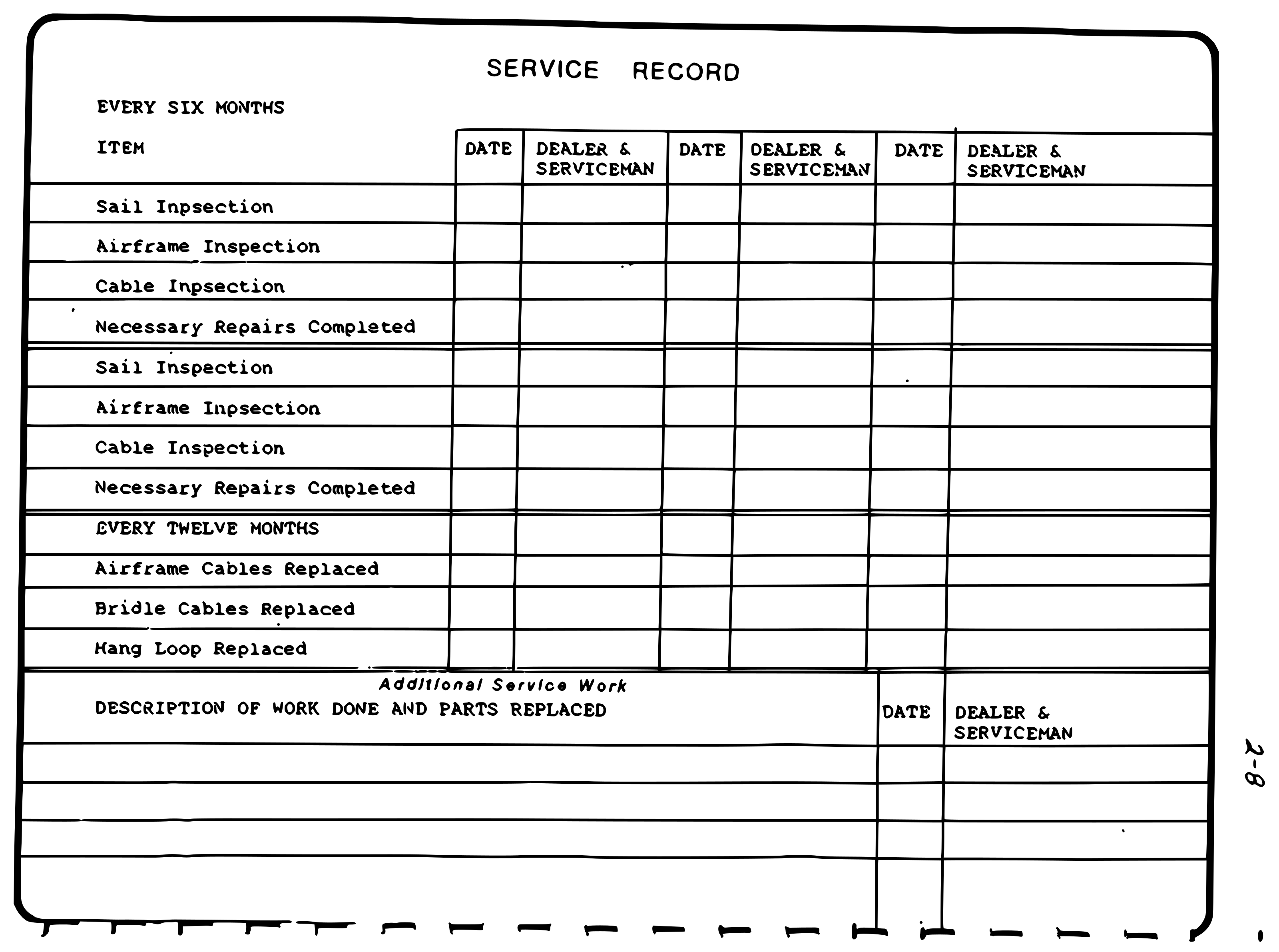
Fill out the service schedule when work is done on the glider.
DISMOUNTING THE FRAME FROM THE SAIL
To remove the sail from the frame:
1) Detach the keel pocket restraining strap.
2) Remove the clevis pin from the control bar "U" channel and detach the control bar from the keel.
3) Detatch the bottom side and lower front to rear wires from the control bar.
4) Remove the kingpost cap from the kingpost and remove each of the top wires from the cap. You will need to remove the black plastic cap and the white plastic retaining rivet by pushing them out from the bottom of the cap with a 1/4" diameter punch.
5) Dismount the sail at the nose, and at the rear leading edges.
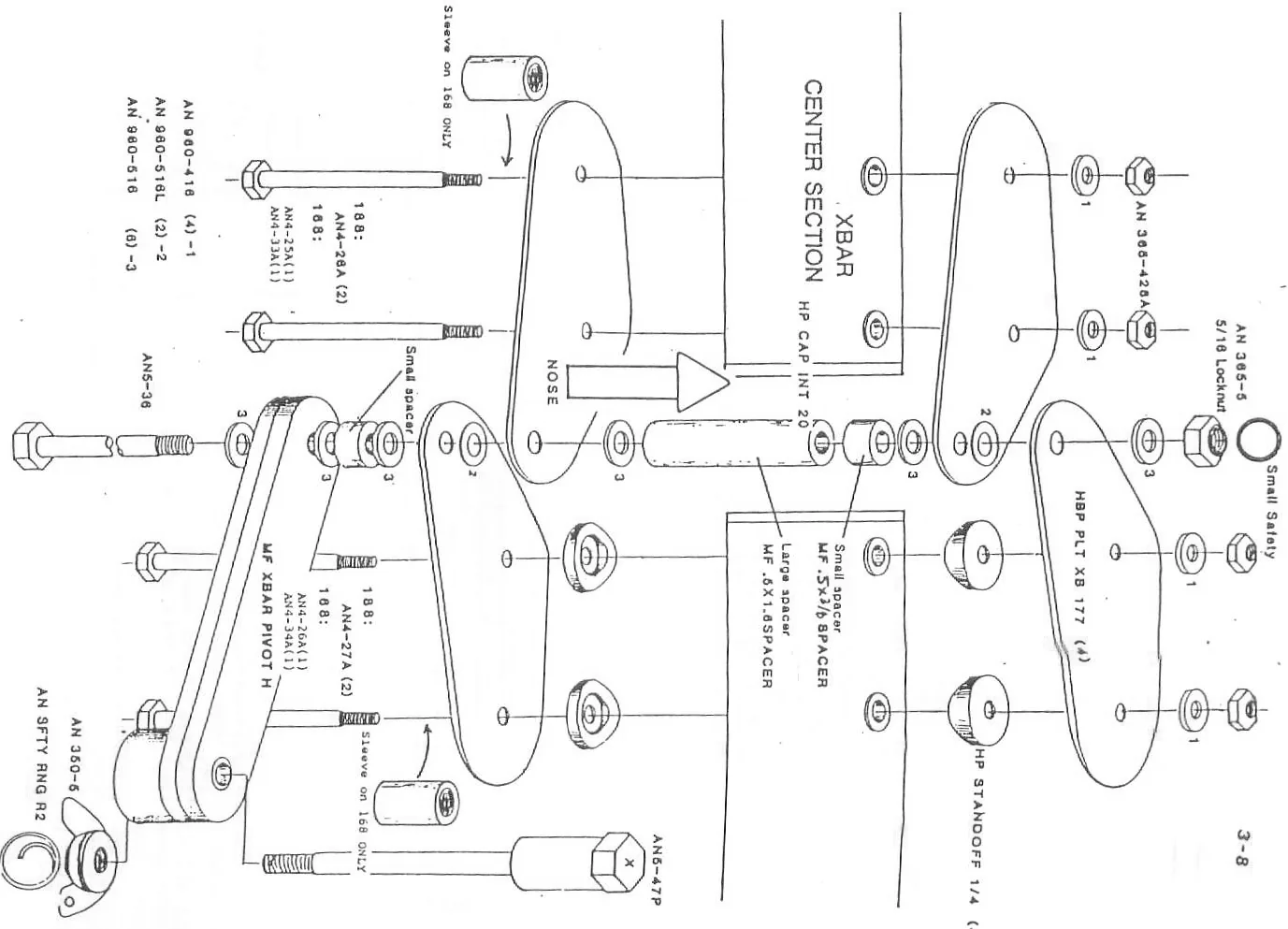
6) Dismount the crossbar halves from the crossbar center section. DO NOT DISASSEMBLE THE NOSE OR THE LEADING EDGE CROSSBAR JUNCTIONS!
7) Swing the crossbar halves to the rear. Carefully slide the frame out through the nose of the sail. (It is best to have a helper at this point.)
Drawing text (as read by OCR, for search)
SERVICE RECORD EVERY SIX MONTHS ITEM DATE DEALER & SERVICEMAN DATE DEALER & SERVICEMAN DATE DEALER & SERVICEMAN Sail Inpsection Airframe Inspection Cable Inpsection Necessary Repairs Completed Sail Inspection Airframe Inpsection Cable Inspection Necessary Repairs Completed EVERY TWELVE MONTHS Airframe Cables Replaced Bridle Cables Replaced Hang Loop Replaced Additional Service Work DESCRIPTION OF WORK DONE AND PARTS REPLACED DATE DEALER & SERVICEMAN 2-8
CONTROL BARS
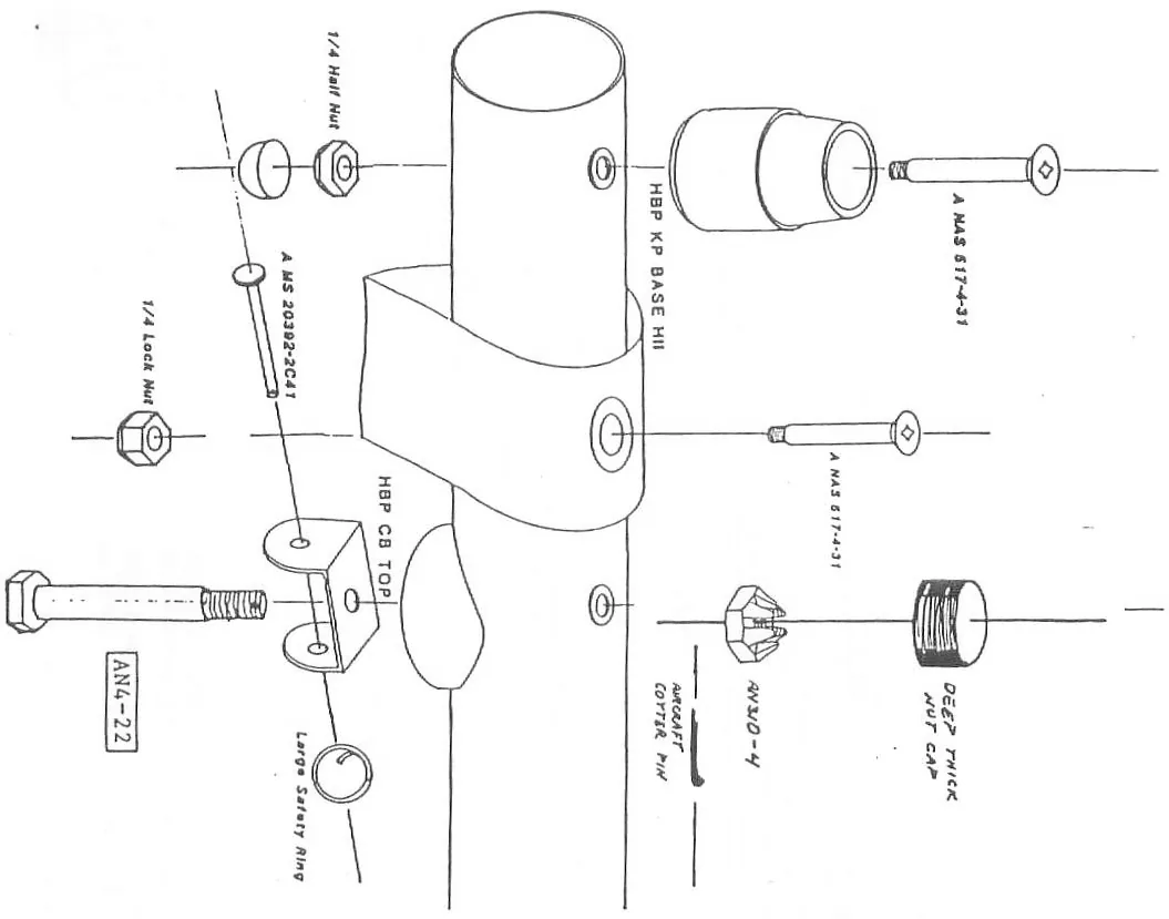
BAR SIZE LEG BASE
| E-63 | 631.125 x .058 | 54.51.125 x .058 |
| E-66 | 66.251.125 x .095 | 57.1251.125 x .058 |
| E-70 | 69.51.125 x .095 | 59.781.125 x .058 |
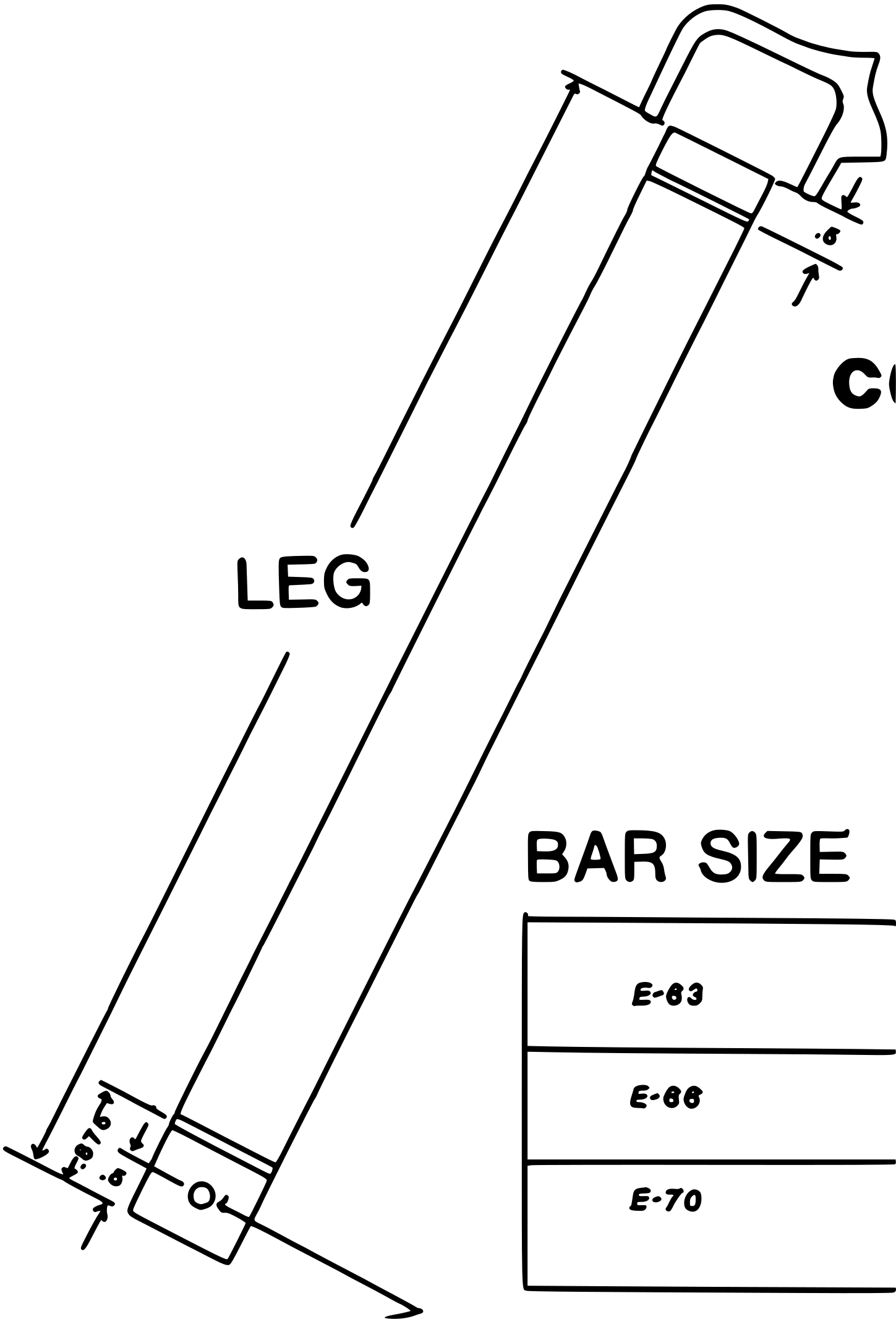
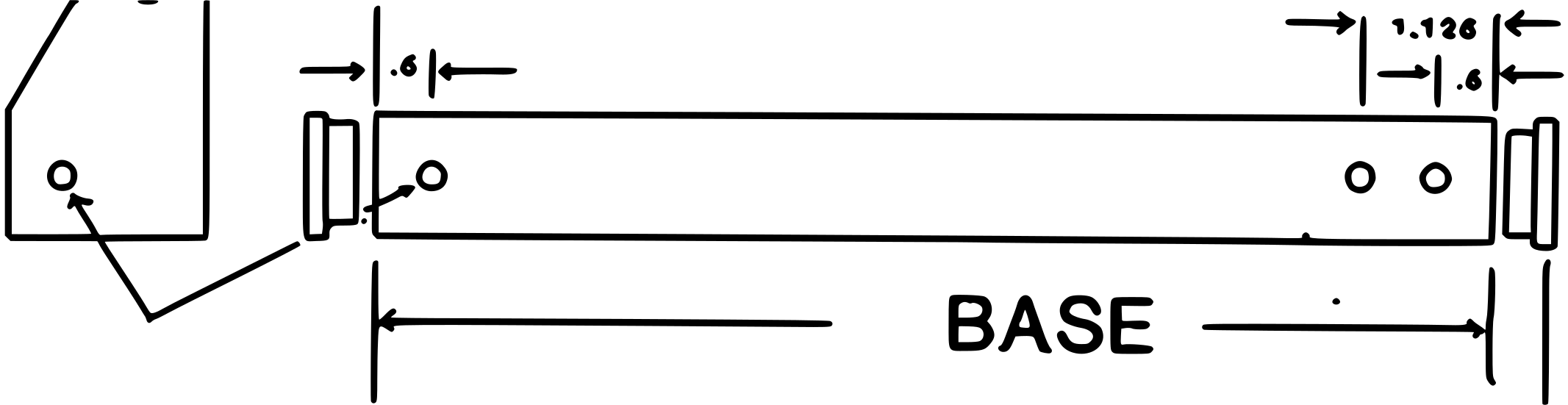
| APPLICATION | |
| E-63 | SKYHAWK 168DUCK 130 HARRIER 147 |
| E-66 | SKYHAWK 188DUCK 160 HARRIER II 177 |
| E-70 | DUCK 180, 200HARRIER I 177 & 187HARRIER II 187 |
CONTROL BAR
3-2
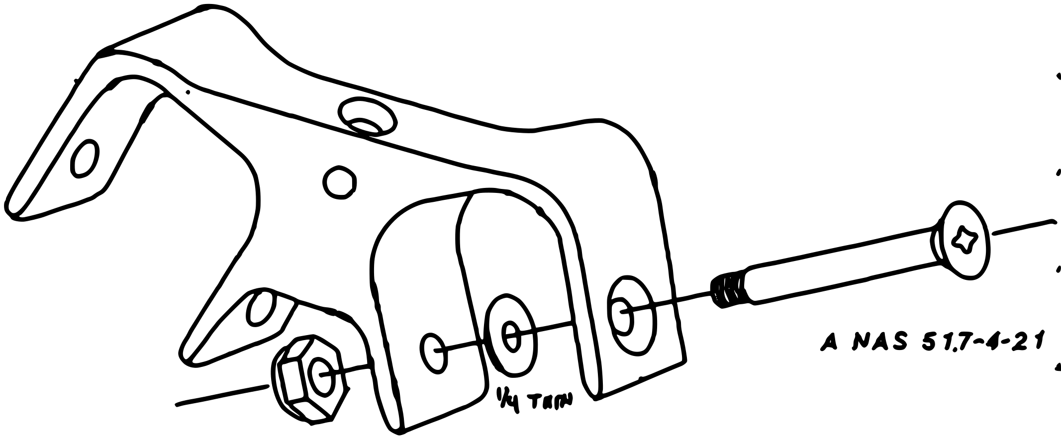
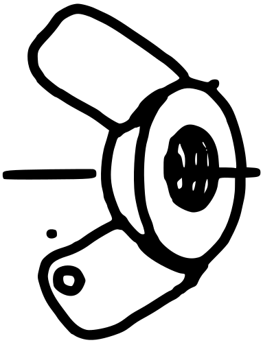
(2 per Duck)
(1 per Harrier)
OR SKYHAWK)
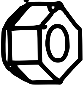
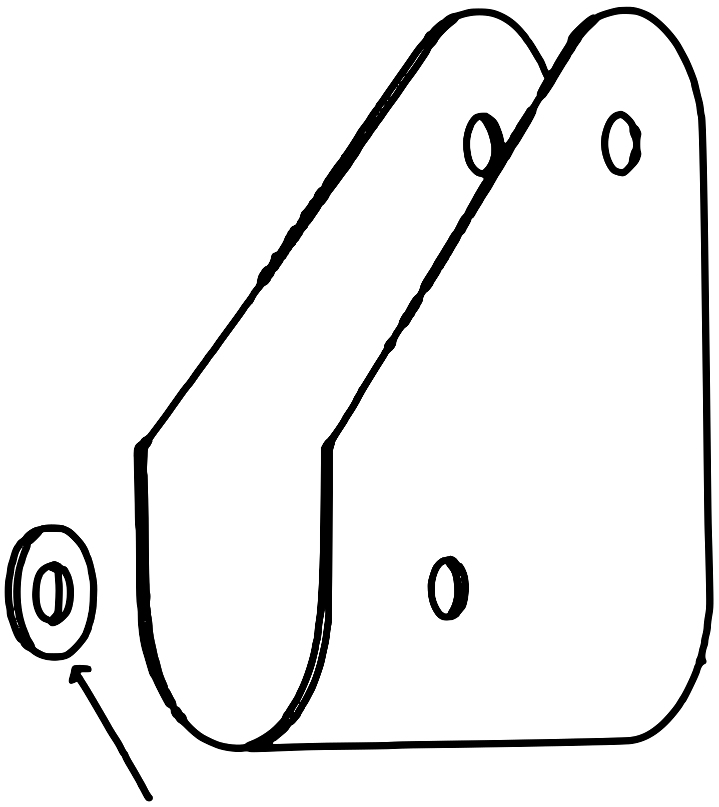
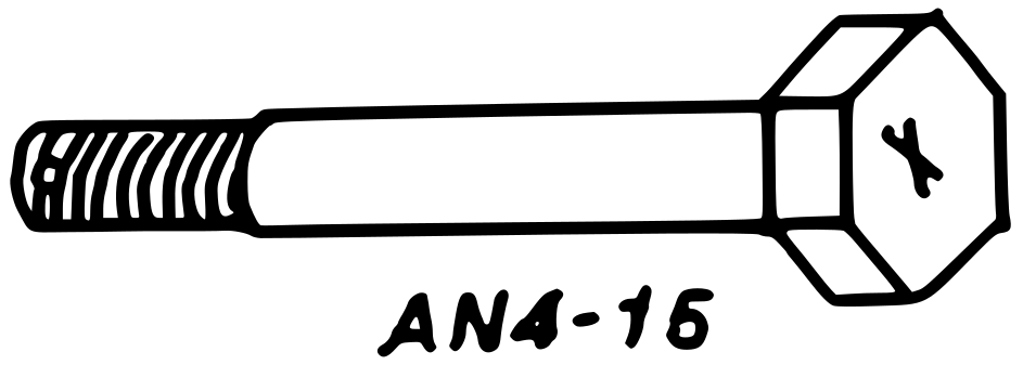
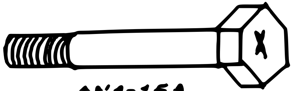
(2 per Duck)
(3 per Harrior)
OR SKYHAWK)
(2 per Duck)
(1 per Harrier)
OR SKYHAWK)
(2 per Duck)
(3 per Harrior)
OR SKYHAWK)
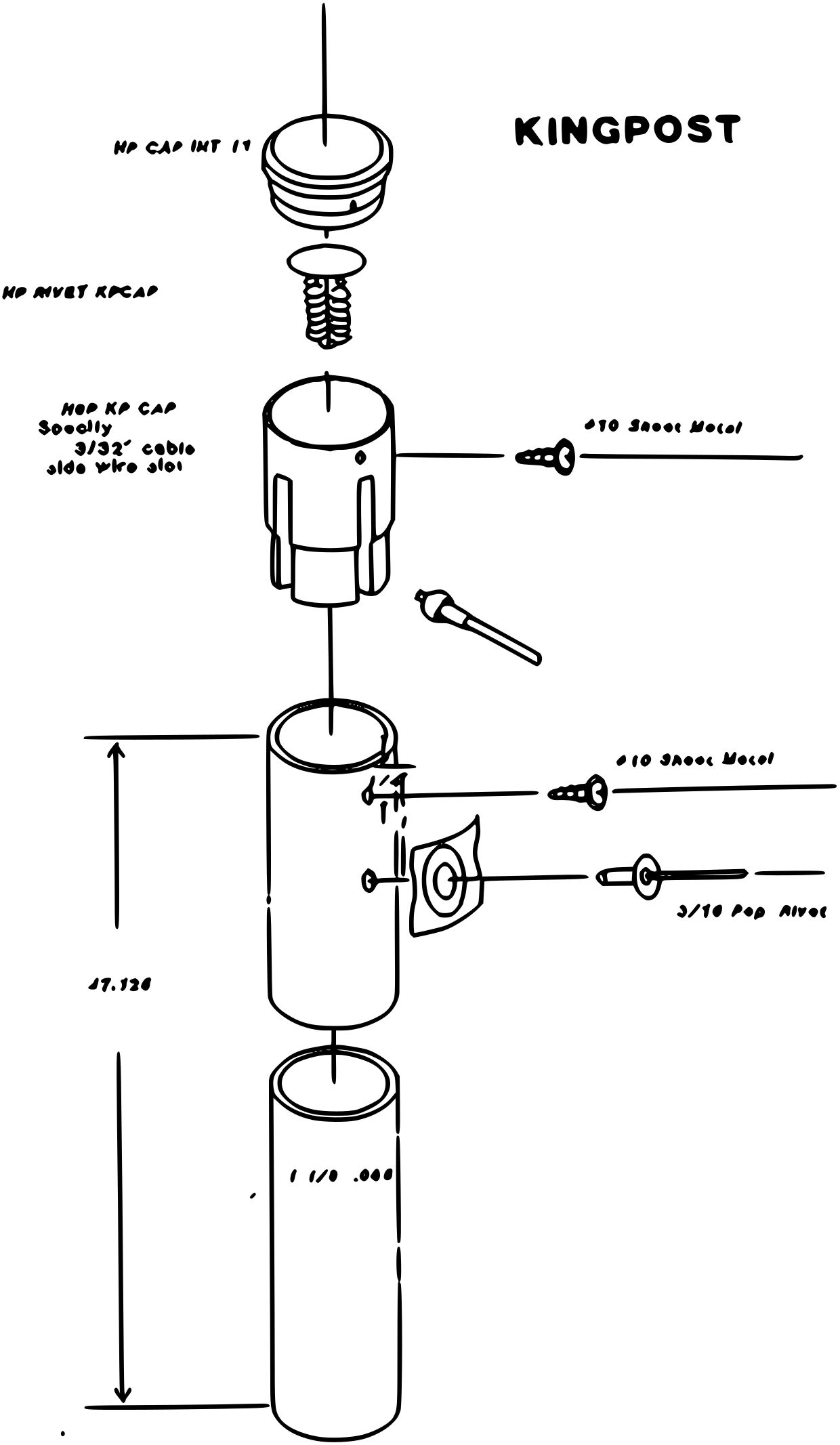
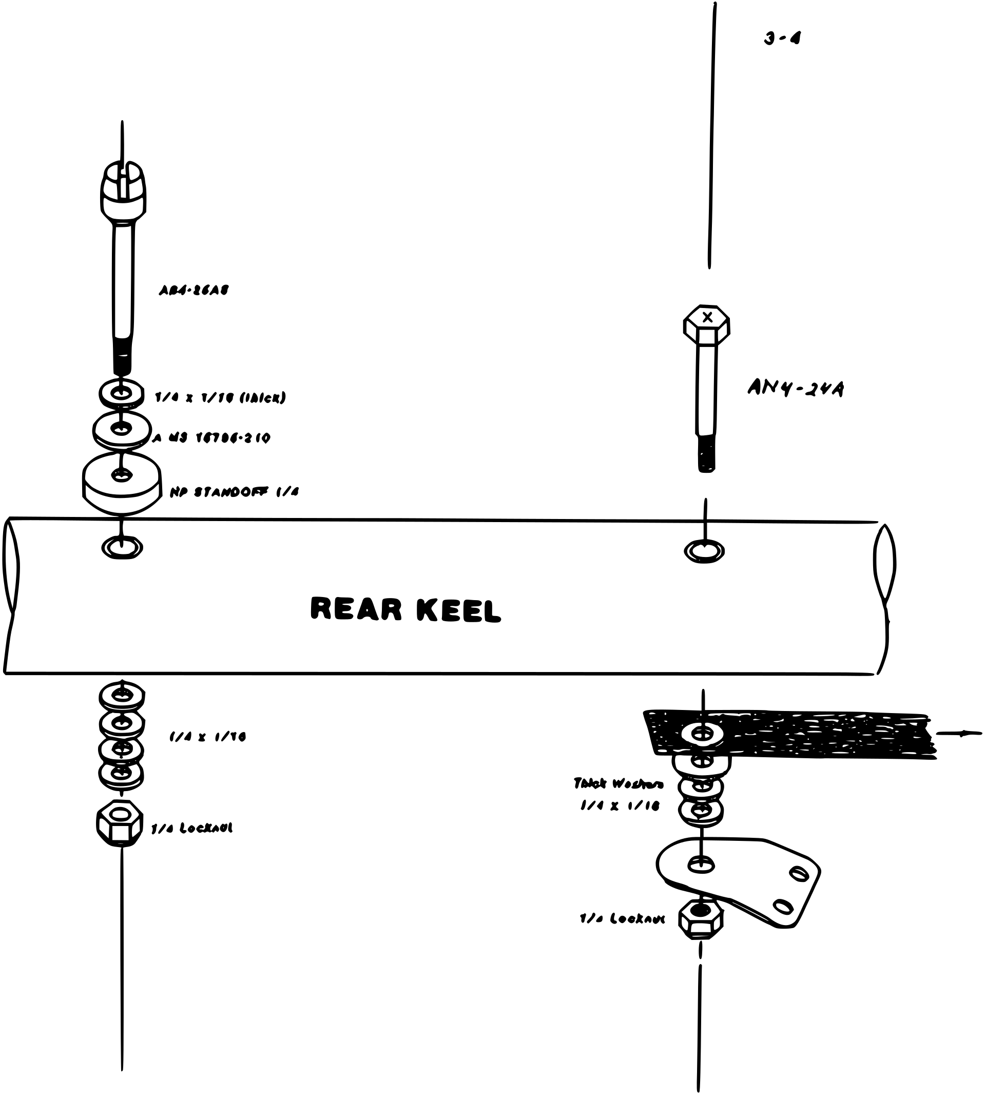
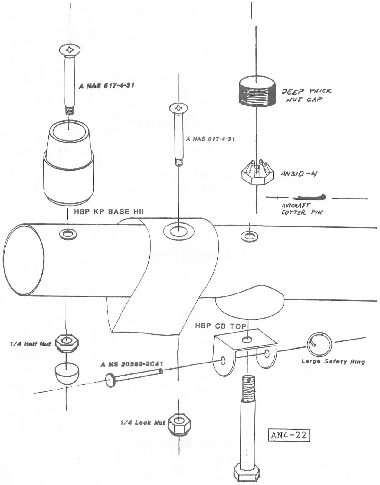
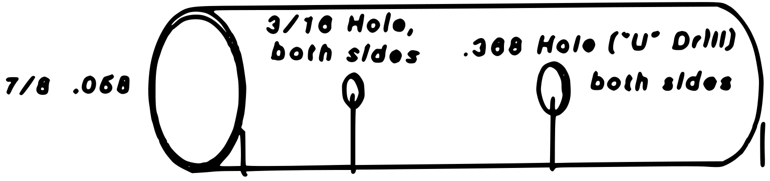
SEE ADBEDUM IN REAR
(Specific GLIDER MODEL)
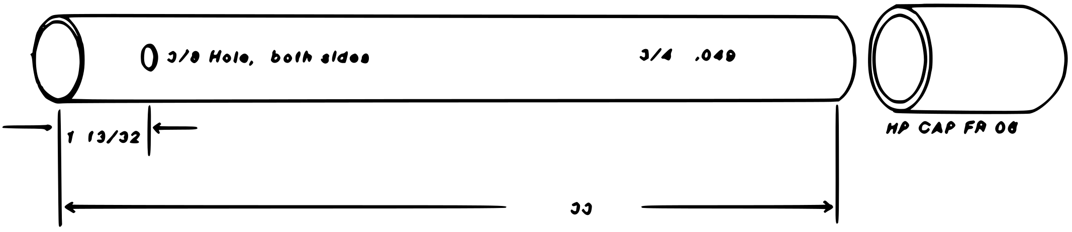
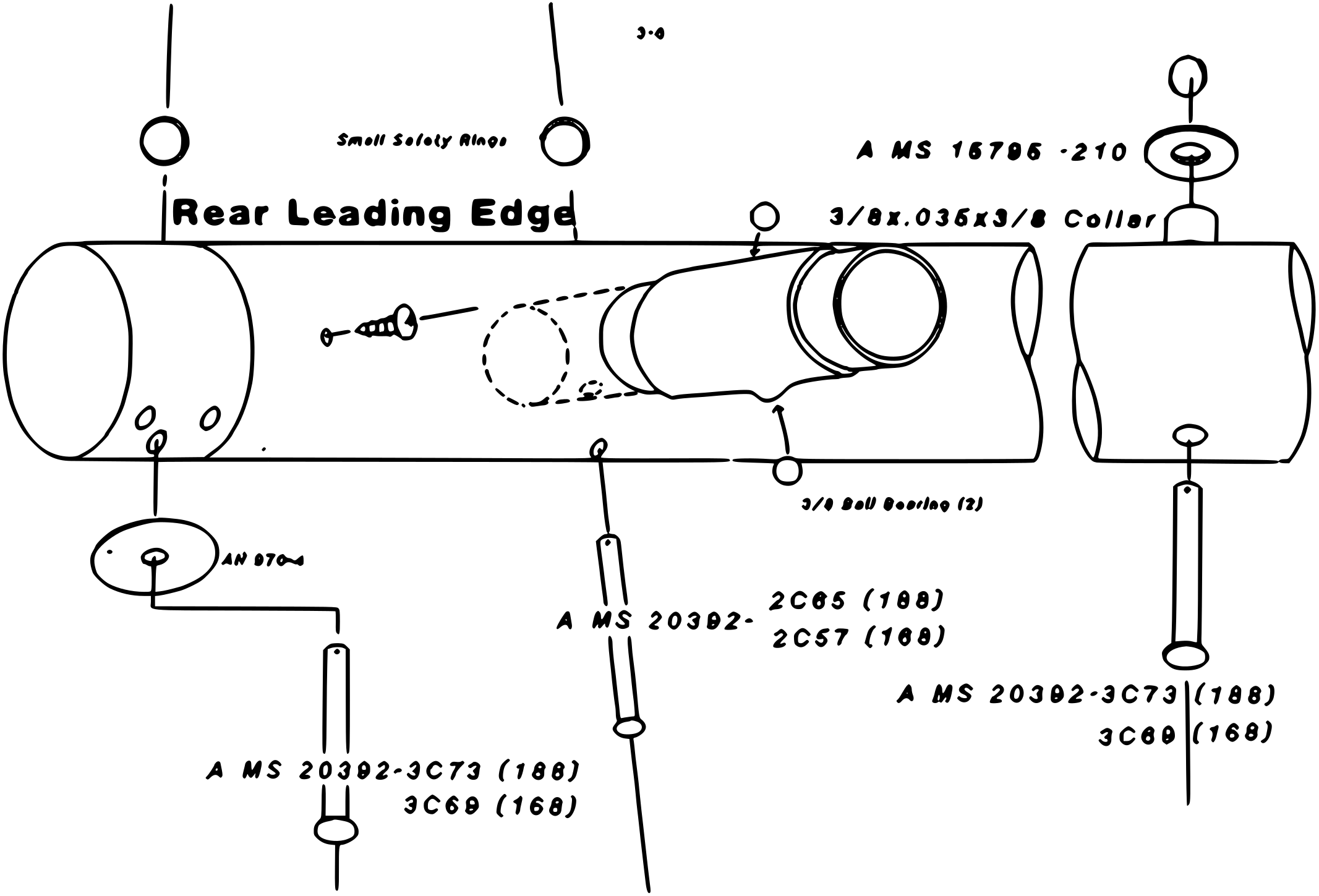
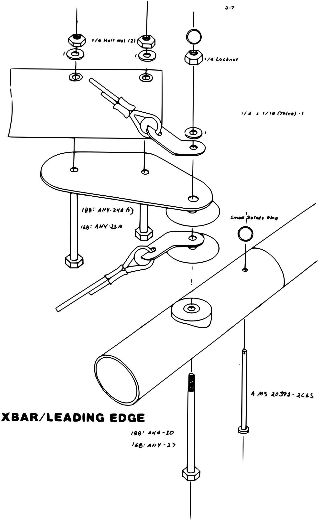
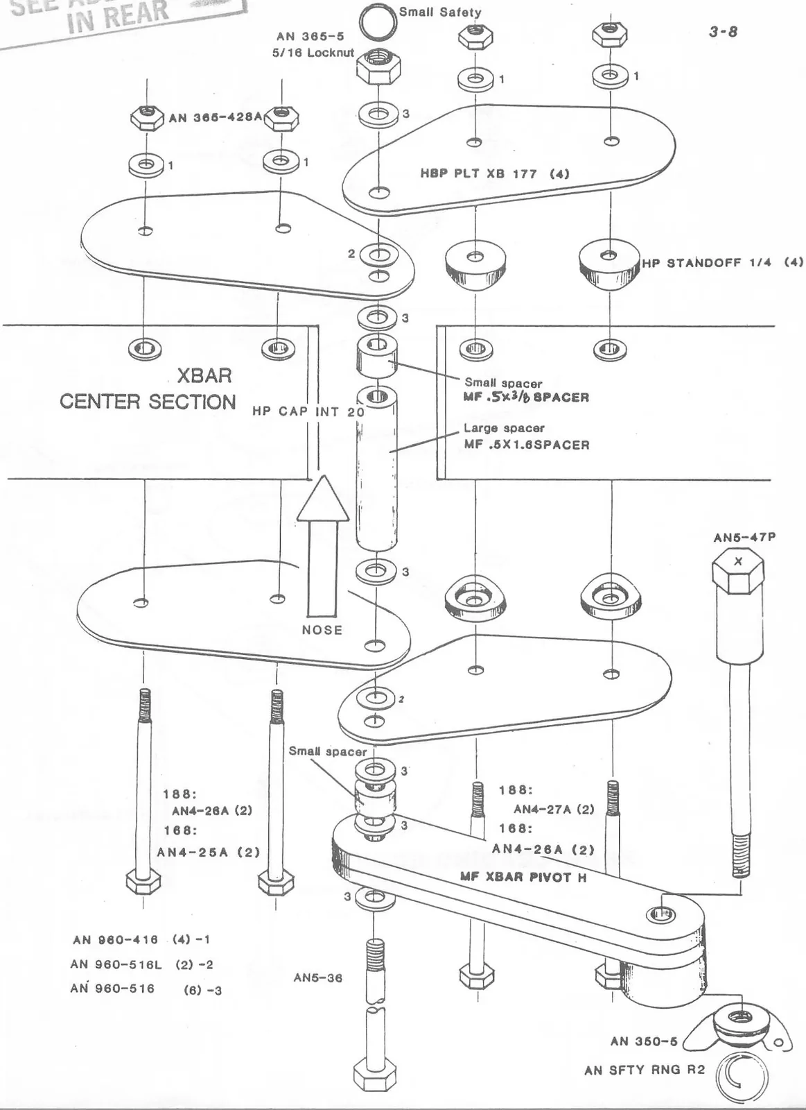
SKYHAWK
188


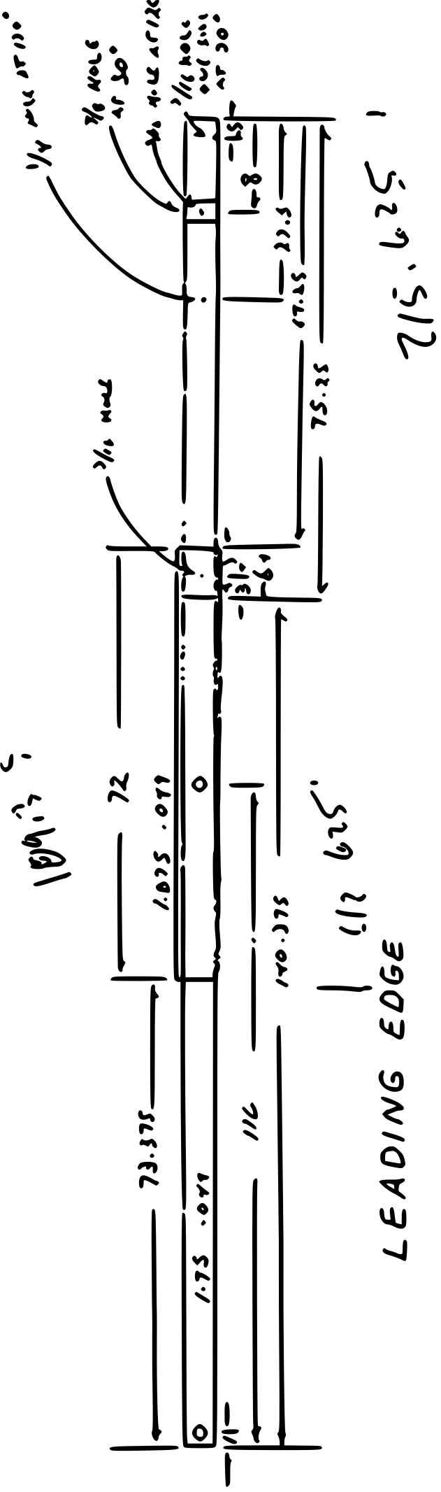
LEADING EDGE
NOTE:
All holes are perpendicular to plane of page unless otherwise noted.
All holes drilled 3/8" and bushed to .305" inside diameter unless otherwise noted.
All dimensions in inches unless otherwise noted.
Drawings not to scale.
SKYHAWK
168
3-13
NOTE:
All holes are perpendicular to plane of page unless otherwise noted.
All holes drilled 3/8" and bushed to .305" inside diameter unless otherwise noted.
All dimensions in inches unless otherwise noted.
Drawings not to scale.
WILLS WING COMPLIANCE VERIFICATION SPECIFICATION SHEET
NOTE: THESE SPECIFICATIONS ARE FOR THE PURPOSE OF VERIFYING THAT THE GLIDER IS IN THE CONFIGURATION IN WHICH IT WAS HGMA CERTIFIED. THEY SHOULD NOT BE USED FOR PARTS FABRICATION.
Glider Model: 168 Skyhawk
1) Glider Weight 60 lbs
(lbs., with bag)
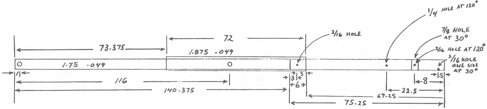
2) Leading Edge Tube Length, Outside Diameter 215.625, 1.75
Holes at: 1, 116, 142.375, 193.125, 207.625, 215.125
Kee1 Tube
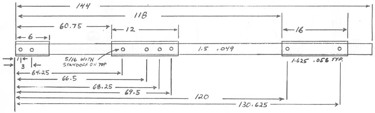
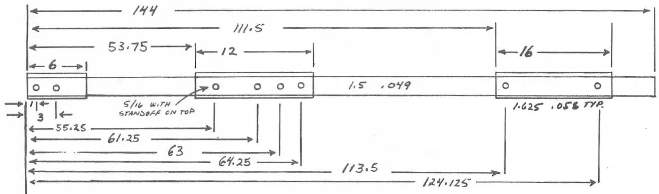
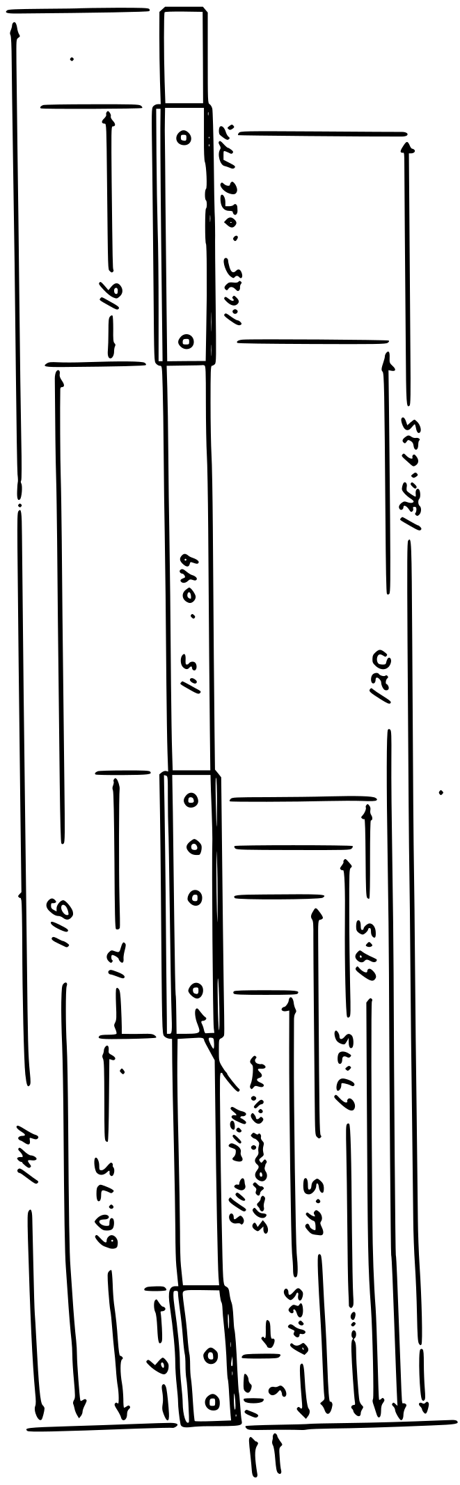
Length, Outside Diameter 144, 1.5
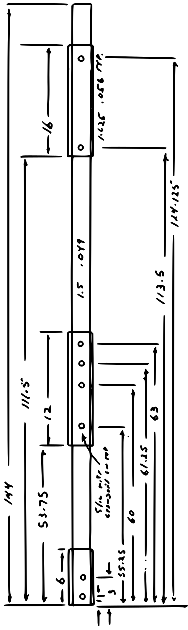
Holes at: 1, 3, 55.25, 61.25, 63, 64.25, 113.5, 124.125
Xbar Tube
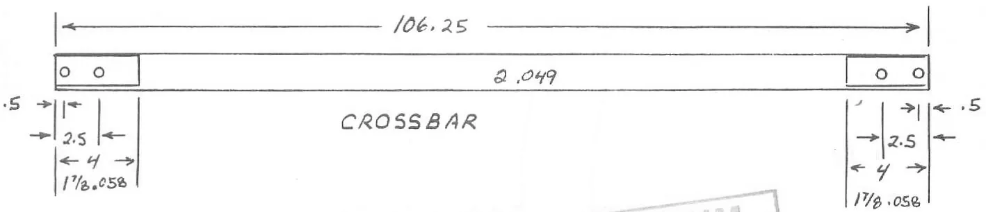
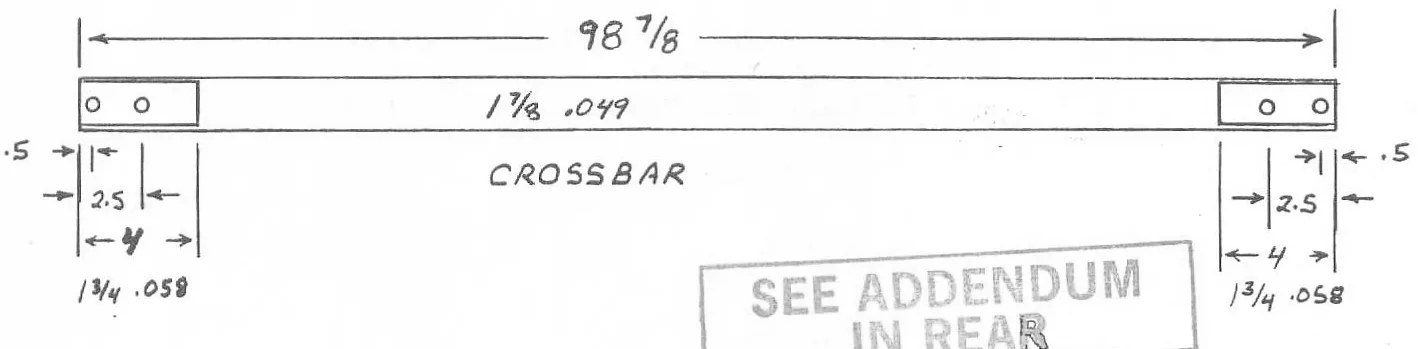
Length, Outside Diameter 98.875, 1.875
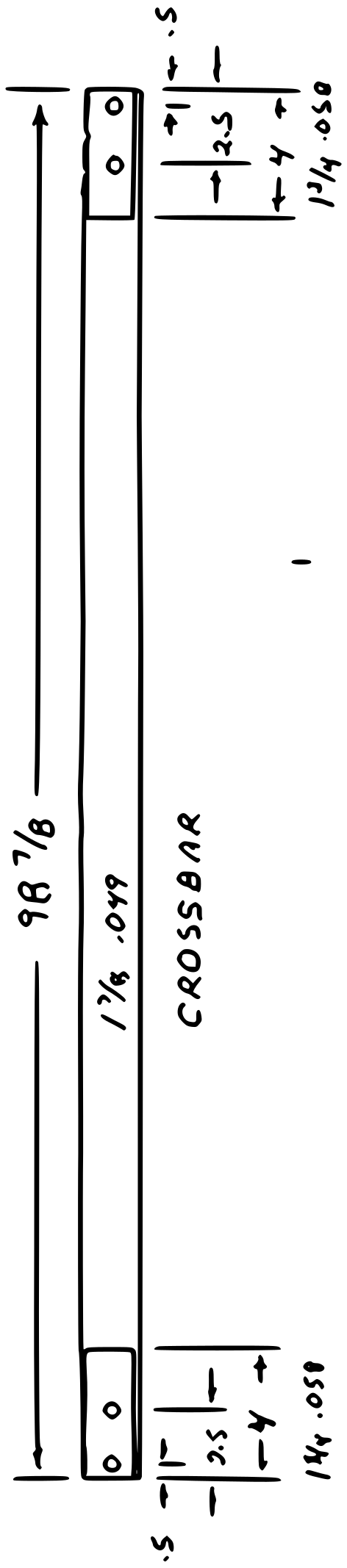
Holes at: .5, 2.5 each end
Kingpost Tube
Length, Outside Diameter 47.125, 1.125
Holes at: .25, 1
Control Bar Leg
Length, Outside Diameter 63, 1.125
Holes at: .5, .875, .5 other end
Control Bar Base
Length, Outside Diameter 54.5, 1.125
Holes at: .5, 1.125, .5 other end
Washout Tips
Length, Outside Diameter 33, .75
Holes at: 1.40625
3) Washout Tip Angle 30 degrees
Control Bar Angle 6.2 degrees
4) Bridle Measurement 75 from top front wire at kingpost cap to pencil line at trailing edge at bridle batten
5) Chord at Root + 3' 82
Chord at Tip - 3' 44
6) Span of Sail 364
7) Bow In Leading Edge approx 2
Bow In Kee1 0
Bow In Crossbar 0
8) Placard Location keel
Test Fly Sticker Location on placard
9) Pilot Weight Range 130 - 190
Pilot Proficiency Required USHGA II or equivalent
Note: All dimensions are in inches unless otherwise stated.
WILLS WING COMPLIANCE VERIFICATION SPECIFICATION SHEET
NOTE: THESE SPECIFICATIONS ARE FOR THE PURPOSE OF VERIFYING THAT THE GLIDER IS IN THE CONFIGURATION IN WHICH IT WAS HGMA CERTIFIED. THEY SHOULD NOT BE USED FOR PARTS FABRICATION.
Glider Model: 188 Skyhawk
SEE ADDENDUM IN REAR
1) Glider Weight 68 (lbs., with bag)
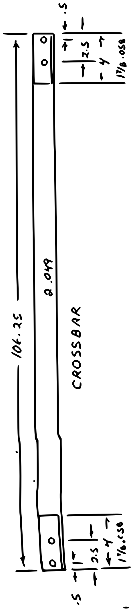
2) Leading Edge Tube Length, Outside Diameter 234 Holes at: 1, 126, 131, 211.5, 226, 233.5 Keel Tube Length, Outside Diameter 144, 1.5 Holes at: 1, 3, 64.25, 66.5, 68.25, 69.5, 120, 130.625 Xbar Tube Length, Outside Diameter 106.25, 2 Holes at: .5, 2.5 each end Kingpost Tube Length, Outside Diameter 47.125, 1.125 Holes at: .25, 1 Control Bar Leg Length, Outside Diameter 66.25, 1.125 Holes at: .5, .875, .5 other end Control Bar Base Length, Outside Diameter 57.125, 1.125 Holes at: .5, 1.125, .5 other end Washout Tips Length, Outside Diameter 33, .75 Holes at: 1.40625
3) Washout Tip Angle 30 degrees Control Bar Angle 1.9 degrees
4) Bridle Measurement 86 from top front wire at cap to pencil line at bridle batten at trailing edge.
5) Chord at Root + 3' 86 Chord at Tip - 3' 44
6) Span of Sail 396
7) Bow In Leading Edge Approx 2 Bow In Keel 0 Bow In Crossbar 0
8) Placard Location keel Test Fly Sticker Location on placard
9) Pilot Weight Range 150 - 235 lbs. Pilot Proficiency Required USHGA II or equivalent
Note: All dimensions are in inches unless otherwise stated.
REFLEX SUPPORT BRIDLES
The proper adjustment for the reflex bridles is just slack in normal flight. The dimensions listed on the compliance verification specification sheet in the rear of this manual give you the normal measurements. However, the "just slack" criterion is the determining factor. This is best determined by flying the glider and sighting the shadow of the bridles on the sail. They should be perceptibly slack, but not more than just slack. Be sure to distinguish between the curved shadow of a straight bridle on the curved surface of the sail, and the shadow of a bridle line which is curved because it is hanging slightly slack. Slack bridles will wiggle when you shake the control bar. If the bridles are too tight, the handling of the glider will be seriously degraded. If they are too loose, the glider will not have the level of pitch stability for which it was designed and certified, and may not be safe. LOOSENING THE BRIDLES BEYOND THE PROPER ADJUSTMENT WILL NOT IMPROVE EITHER HANDLING OR PERFORMANCE.
FRONT TO REAR WIRE LOOP LENGTH ADJUSTMENT
There are washers stacked underneath some of the nuts and bolts that attach the wires to the keel. Redistribution of one or more of these washers will allow for some adjustment of the tension in the front to rear wire loop. This loop should be snug, but not so tight that you have difficulty attaching or removing the keyhole tang from the top rear wire bolt. Following the removal or addition of washers you should install a new nylock nut, and check to see that at least one or more threads protrude from the nylon in the nut after installation. If you cannot achieve the desired adjustment in this manner, order a longer or shorter top rear wire from the factory.
LEADING EDGE SAIL TENSION
The leading edge sail mount plug has three holes for the adjustment of leading edge sail tension. The provision for tensioning the sail tighter than normal is primarily intended to retention older sails which may have stretched along the leading edge. Tightening the sail will tend to slightly improve performance, but tends to make the glider stiffer and slower to turn, and to increase the tendency for adverse yaw. Loosening the leading edge sail tension is usually the single most effective way to improve the handling of a stiff, slow rolling glider. (Check first to see that all other adjustments are properly set.) However, loosening the sail beyond a certain point will make handling worse rather than better. When remounting the sail to a different hole in the plug, make sure to rotate the plug appropriately so as to maintain the proper amount of twist in the tip. Also make sure to secure the plug with the set screw following any such adjustments. (See the appropriate diagrams in the back of this section.)
If you loosen the sail, make sure to loosen the number one plug-in batten strings, or else they will be too tight.
LEADING EDGE SAIL MOUNT PLUG
This plug can be rotated to change the effective twist in the wing tip. Adjusting this twist is the most effective way to correct for a tendency of the glider to turn to one side. The normal adjustment results in the sail mount clevis pin being almost parallel (see diagram) to the washout tip sleeve. Rotating the plug so as to twist the trailing edge up (Clockwise for the right tip) will make the glider turn towards that wing, while rotating the plug so as to reduce twist in that wing will make the glider turn away from that wing. When adjusting for a turn, you may find that decreasing the twist in one wing is more effective than increasing the twist in the other wing. Whenever changing this adjustment, do so in small increments, and make sure to re-secure the plug with the set screw. Rotating both tips up will tend to reduce the trim speed, increase the pitch bar pressure, and make the glider more roll stable. You should not rotate BOTH tips down below the point where the clevis pins are parallel to the washout tip sleeves, nor should you rotate either tip down to the point where there is less than 1" clearance between the sail and the end of the washout tip in flight at trim speed. You should not have to rotate either tip more than one notch away from the stock adjustment. If the glider cannot be properly trimmed without doing so, call the factory.
HANG LOOP
The hang loop can be swapped with the kingpost base to increase the glider's trim speed if necessary. (Some Skyhawks may come this way from the factory if they indicated a low trim speed on the test flight.) The hang loop position is very important to proper handling on the Skyhawk; if it is too far aft, the glider will be much stiffer in roll than it was designed to be. Because the Skyhawk is very controllable in a partially stalled, mushing angle of attack mode, it is often not apparent that the hang loop is set too far back. If you notice that the glider is sometimes stiff to roll into a thermal, or, if once in a turn the glider has a tendency to roll to a steeper bank or resist rolling out, try moving the hang loop forward before you experiment with any other tuning adjustments.
WILLS WING COMPLIANCE VERIFICATION SPECIFICATION SHEET
NOTE: THESE SPECIFICATIONS ARE FOR THE PURPOSE OF VERIFYING THAT THE GLIDER IS IN THE CONFIGURATION IN WHICH IT WAS HGMA CERTIFIED. THEY SHOULD NOT BE USED FOR PARTS FABRICATION.
Glider Model: 168 Skyhawk
1) Glider Weight 60 lbs (lbs., with bag)
2) Leading Edge Tube Length, Outside Diameter 215.625, 1.75 Holes at: 1, 116, 142.375, 193.125, 207.625, 215.125 Keel Tube Length, Outside Diameter 144, 1.5 Holes at: 1, 3, 55.25, 60, 61.25, 63, 113.5, 124.125 Xbar Tube Length, Outside Diameter 98.875, 1.875 Holes at: .5, 2.5 each end Kingpost Tube Length, Outside Diameter 47.125, 1.125 Holes at: .25, 1 Control Bar Leg Length, Outside Diameter 63, 1.125 Holes at: .5, .875, .5 other end Control Bar Base Length, Outside Diameter 54.5, 1.125 Holes at: .5, 1.125, .5 other end Washout Tips Length, Outside Diameter 33, .75 Holes at: 1.40625
3) Washout Tip Angle 30 degrees Control Bar Angle 6.2 degrees
4) Bridle Measurement 75 from top front wire at kingpost cap to pencil line at trailing edge at bridle batten
5) Chord at Root + 3' 82 Chord at Tip - 3' 44
6) Span of Sail 364
7) Bow In Leading Edge approx 2 Bow In Keel 0 Bow In Crossbar 0
8) Placard Location keel Test Fly Sticker Location on placard
9) Pilot Weight Range 130 - 190 Pilot Proficiency Required USHGA II or equivalent
Note: All dimensions are in inches unless otherwise stated.
WILLS WING COMPLIANCE VERIFICATION SPECIFICATION SHEET
NOTE: THESE SPECIFICATIONS ARE FOR THE PURPOSE OF VERIFYING THAT THE GLIDER IS IN THE CONFIGURATION IN WHICH IT WAS HGMA CERTIFIED. THEY SHOULD NOT BE USED FOR PARTS FABRICATION.
Glider Model: 188 Skyhawk
1) Glider Weight 68 (1bs., with bag)
2) Leading Edge Tube Length, Outside Diameter 234 Holes at: 1, 126, 131, 211.5, 226, 233.5 Keel Tube Length, Outside Diameter 144, 1.5 Holes at: 1, 3, 64.25, 66.5, 67.75 69.5, 120, 130.625 Xbar Tube Length, Outside Diameter 106.25, 2 Holes at: .5, 2.5 each end Kingpost Tube Length, Outside Diameter 47.125, 1.125 Holes at: .25, 1 Control Bar Leg Length, Outside Diameter 66.25, 1.125 Holes at: .5, .875, .5 other end Control Bar Base Length, Outside Diameter 57.125, 1.125 Holes at: .5, 1.125, .5 other end Washout Tips Length, Outside Diameter 33, .75 Holes at: 1.40625
3) Washout Tip Angle 30 degrees Control Bar Angle 1.9 degrees
4) Bridle Measurement 86 from top front wire at cap to pencil line at bridle batten at trailing edge.
5) Chord at Root + 3' 86 Chord at Tip - 3' 44
6) Span of Sail 396
7) Bow In Leading Edge Approx 2 Bow In Keel 0 Bow In Crossbar 0
8) Placard Location keel. Test Fly Sticker Location on placard
9) Pilot Weight Range 150 - 235 lbs. Pilot Proficiency Required USHGA II or equivalent
Note: All dimensions are in inches unless otherwise stated.
SKYHAWK
188
3-12

KEEL CENTER